Eureka AIR delivers breakthrough ideas for toughest innovation challenges, trusted by R&D personnel around the world.

Method of manufacturing brake pedal coil printed circuit board for vehicle

a technology of printed circuit board and brake pedal, which is applied in the direction of printed element electric connection formation, mechanical control devices, instruments, etc., can solve the problems of time and collision accidents, and achieve the effect of quick sens

Inactive Publication Date: 2017-01-12
JEONG CHANBOUNG
View PDF5 Cites 7 Cited by
  • Summary
  • Abstract
  • Description
  • Claims
  • Application Information

AI Technical Summary

Benefits of technology

The present invention aims to solve the issues of the prior art by providing a method for manufacturing a brake pedal coil printed circuit board for vehicles that allows a wireless sensor to quickly detect if the driver applies physical energy to the foot brake pedal to turn on the rear brakes.

Problems solved by technology

However, since conventional rear brake lights are turned on only when a driver steps on a foot brake pedal (physical energy is applied to the foot brake pedal), there is a risk of collision accidents when a driver suddenly steps on the foot brake and drivers of the cars behind do not keep a sufficient distance between cars.
That is, the conventional rear brake lights have drawbacks in that, when a driver steps on a foot brake pedal, time is required to turn on rear brake lights due to a brake spacing (a gap between a brake lining and a disk over which the brake lining pushed by a fluid pressure in a master cylinder travels to reach the disk when a driver steps on the foot brake pedal) and, when a driver keeps foot on the foot brake pedal, time is required to transmit signals through wires in order to turn on the rear brake lights.

Method used


Image

  • Method of manufacturing brake pedal coil printed circuit board for vehicle
  • Method of manufacturing brake pedal coil printed circuit board for vehicle
  • Method of manufacturing brake pedal coil printed circuit board for vehicle

Examples


Embodiment Construction

[0034]Various changes and modifications can be made to the present invention, which can include various exemplary embodiments. Therefore, certain embodiments of the present invention will be shown in the drawings and described in the detailed description. However, it should be understood that the certain embodiments proposed herein are not intended to limit the scope of the invention and cover all such changes and modifications within the scope of the appended claims and their equivalents. In describing the present invention, detailed descriptions of the prior art related to the present invention will be omitted for clarity when the detailed descriptions are considered to obscure the gist of the present invention.

[0035]Also, it should be understood that, although the terms first, second, etc. may be used herein to describe various elements, these elements should not be limited by these terms. These terms are used only to distinguish one element from another.

[0036]In addition, it wil...


PUM


Abstract

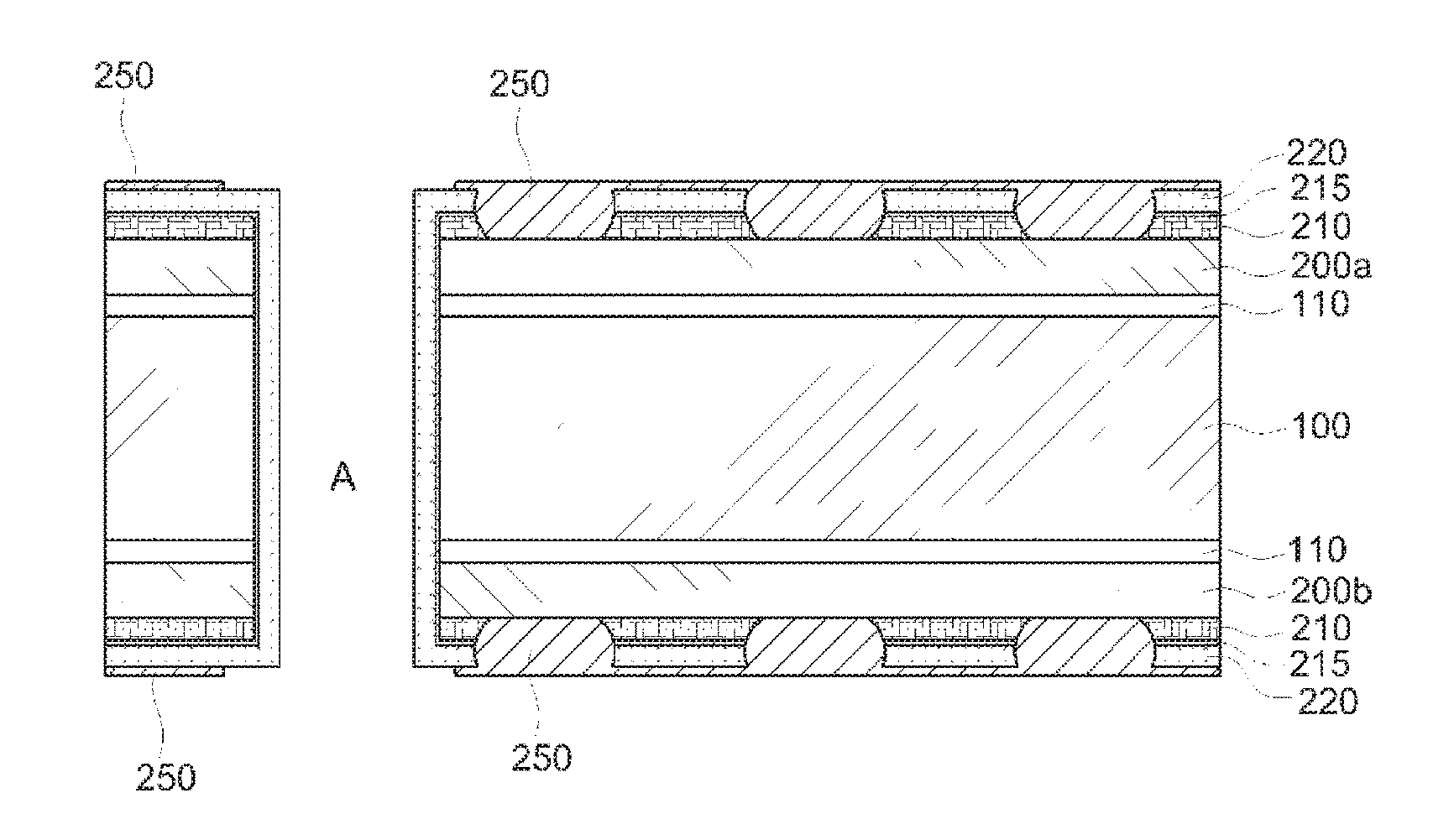
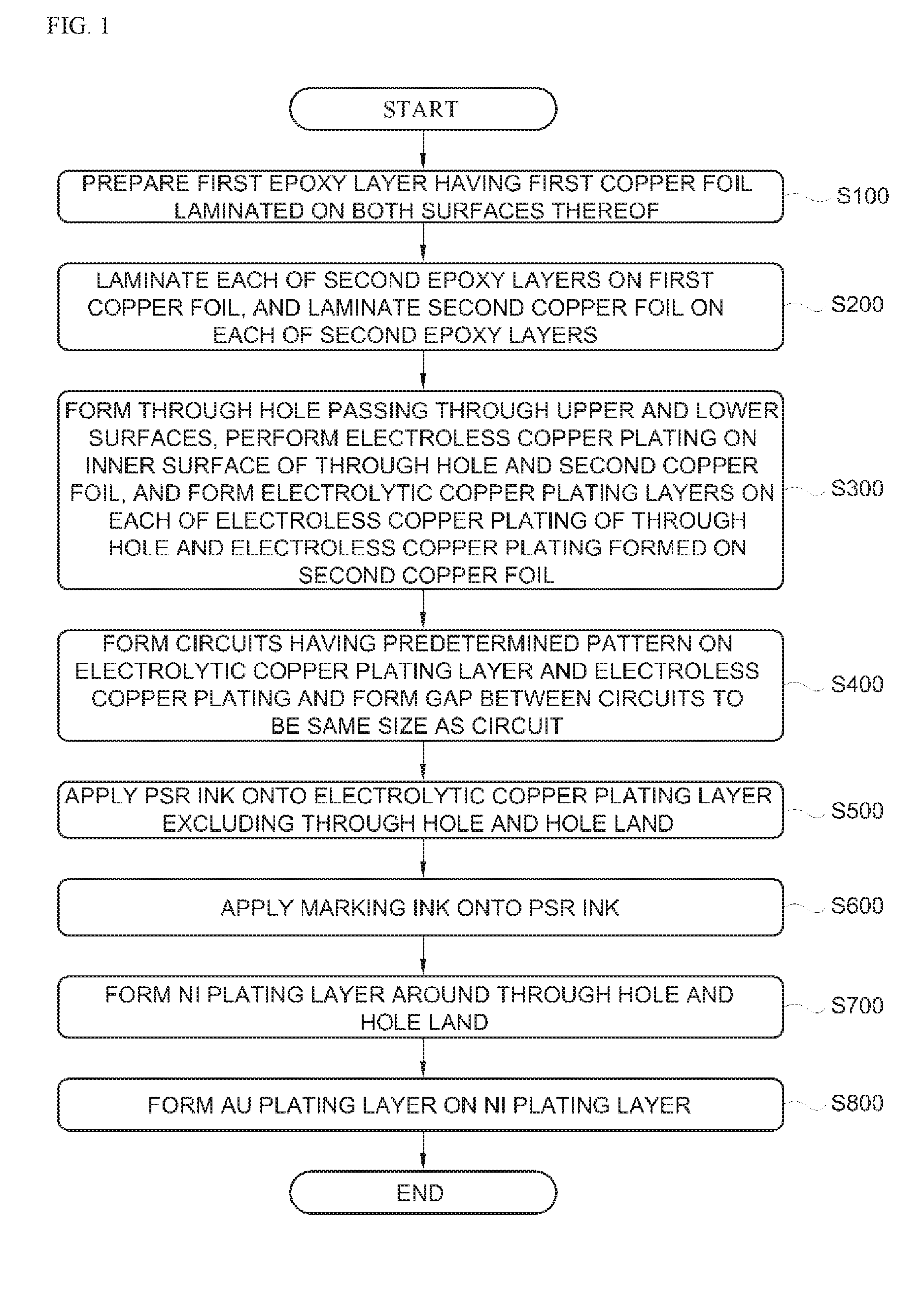
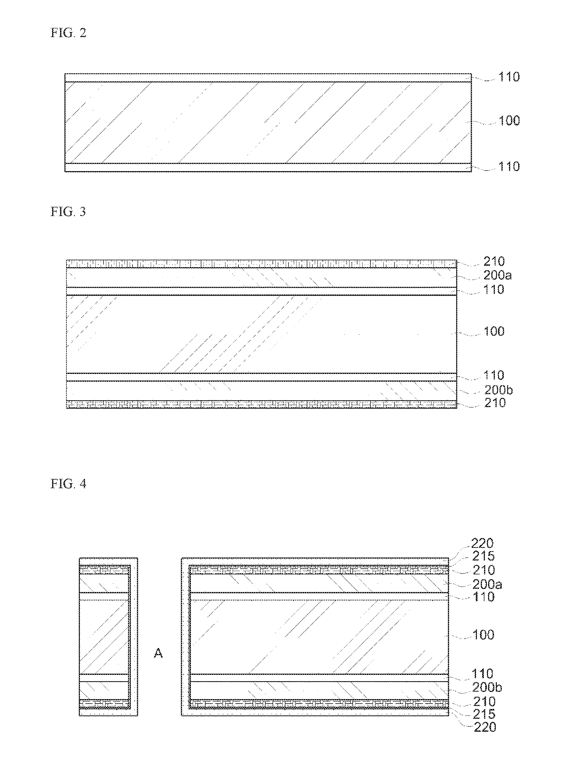
A method of manufacturing a brake pedal coil printed circuit board for vehicles is provided which is capable of allowing a wireless sensor to quickly sense whether physical energy from a driver is applied to a foot brake pedal to turn on rear brake lights. To solve the above problems, the method of manufacturing a brake pedal coil printed circuit board for vehicles includes preparing a first epoxy layer (100) having first copper foil (110) laminated on both surfaces thereof (S100), laminating each of second epoxy layers (200a and 200b) on the first copper foil (110), and laminating second copper foil (210) on each of the second epoxy layers (200a and 200b) (S200), forming a through hole (A) passing through upper and lower surfaces, performing electroless copper plating on an inside surface of the through hole (A) and the second copper foil (210), and forming an electrolytic copper-plated layer (220) on each of the electroless copper-plated layer (215) of the through hole (A) and the electroless copper-plated layer (215) formed on the second copper foil (210) (S300), forming circuits having a predetermined pattern on the electrolytic copper-plated layer (220) and the electroless copper-plated layer (215) and forming a gap between the circuits to have the same size as the circuits (S400), applying a PSR ink (250) onto the electrolytic copper-plated layer (220) (S500), applying a marking ink (260) onto the PSR ink (250) (S600), forming a nickel (Ni)-plated layer (230) around the through hole (A) and the hole land (S700), and forming an Au-plated layer (240) on the Ni-plated layer (230) (S800).

Description

CROSS-REFERENCE TO RELATED APPLICATIONS[0001]This application claims priority to and the benefit of Korean Patent Application No. 10-2015-0097257, filed on Jul. 8, 2015, the disclosure of which is incorporated herein by reference in its entirety.BACKGROUND[0002]Field of the Invention[0003]The present invention relates to a method of manufacturing a brake pedal coil printed circuit board for vehicles, and more particularly, to a method of manufacturing a brake pedal coil printed circuit board for vehicles which, when a driver in front suddenly stops a car during driving or suddenly hits the brake for a sudden slow down, is capable of allowing drivers of cars behind to quickly see and determine the critical situation.[0004]Description of the Related Art[0005]In general, brake lights for vehicles include rear brake lights which are turned on when a driver steps on the foot brake and hand brake lights arranged on a car dashboard which are turned on when a driver engages the hand brake, ...

Claims


Application Information

Patent Timeline
Patent Type & Authority Applications(United States)
IPC IPC(8): B60Q1/44H05K3/06H05K3/18H05K3/42
CPCB60Q1/441H05K3/429B60T7/04H05K3/067H05K3/188H05K3/422B60T7/042B60T7/06H05K2203/072H05K2203/0723G05G1/30
Inventor JEONG, CHANBOUNG
Owner JEONG CHANBOUNG
Why Eureka
Eureka Blog
Learn More