Sensing artifact reduction for cardiac diagnostic system

a diagnostic system and artifact technology, applied in the field of detection of patients' susceptibility to cardiac arrhythmias, can solve the problems that the existing cardiac sensing circuitry is generally not designed to allow effective sensing of cardiac signals, and achieve the effects of enhancing utility and versatility, increasing stimulation energy, and determining a patient's susceptibility

Active Publication Date: 2006-03-21
HARBINGER MEDICAL
View PDF11 Cites 6 Cited by
  • Summary
  • Abstract
  • Description
  • Claims
  • Application Information

AI Technical Summary

Benefits of technology

[0013]The system involves the use of shunting and impedance switching techniques in the detection of the direct and immediate response to a subthreshold electrical stimulation. Existing artifact reduction techniques for cardiac sensing circuitry following an electrical stimulation are geared around the detection of a residual state or rhythm following that stimulation. In the case of defibrillation, the therapy is delivered and some time later an evaluation is done to determine if the rhythmic state of the heart had been altered back to a normal sinus rhythm. In the case of pacing, an evaluation of whether there was an effective “capture” of the pacing pulse, is made in order to determine whether there is a need for increased stimulation energy.
[0014]In contrast, the present invention involves assessing the patient's immediate response to stimulation and using this diagnostic assessment to determine a patient's susceptibility to future cardiac arrhythmias, as opposed to determining the efficacy of a just delivered therapy. As such, the present invention relates to diagnostic cardiac procedures, and not to evaluating the effectiveness of therapeutic measures.
[0015]The present invention may desirably be placed in an adapter inserted between the cardiac leads and a conventional cardiac sensing apparatus, or the present invention can be incorporated directly into a lead assembly that will be plugged into a cardiac sensing apparatus. By incorporating the artifact reduction techniques of the present invention within an adapter or within a lead assembly, the present invention allows the software techniques for analyzing subtle cardiac phenomenon such as the Wedensky effect to be performed on conventional equipment. Preferably, the techniques of the present invention are automatically enabled so as to further enhance the utility and versatility of enabling existing conventional equipment to perform improved cardiac diagnostic techniques.
[0016]One embodiment of this invention places a mechanism within an electrical lead set connector that allows the lead set to actively reduce sensing artifacts. This involves placing an electrical shunting switch across the conductors of the stimulating and ECG sensing leads. Additionally, solid state impedance switches are placed in series with the sensing leads. The lead set connector may be a part of the disposable lead, an adapter, or within a cable.
[0017]Preferably, the shunt circuit across the stimulation leads automatically activates at the end of the stimulation for a short period of time of less than about 10 ms. This shunting allows residual energy stored on the leads to dissipate through the shunt connection. The impedance switches automatically switch to a high impedance during the application of stimulation energy. This high impedance restricts the flow of energy into the sensing leads. The impedance switches automatically returns to a low impedance following the termination of the shunting of stimulation leads. The shunt circuit across the ECG leads automatically activates during stimulation. Power for the active elements (current detector, shunt, impedance switches) may be via an embedded battery, a separate external power supply, or an additional conductor from the host system. Timing of the shunt and switch activation are provided via a sensitive current sensing circuit in the lead connector which identifies when current is flowing through the stimulation leads.
[0018]The present invention enhances the effective performance of the cardiac sensing circuitry in a conventional high resolution ECG system by enabling for faster recovery and sensing following stimulation. By placing the shunt circuit and impedance switches within the lead connector, or adaptor, the use of a conventional ECG amplifier for measuring subthreshold Wedensky phenomena modulation becomes possible.

Problems solved by technology

As a result, existing cardiac sensing circuitry generally is not designed to allow for effective sensing of cardiac signals during the brief period of less than about 100 milliseconds immediately following delivery of electrical stimulation energy.

Method used


Image

  • Sensing artifact reduction for cardiac diagnostic system
  • Sensing artifact reduction for cardiac diagnostic system
  • Sensing artifact reduction for cardiac diagnostic system

Examples


Embodiment Construction

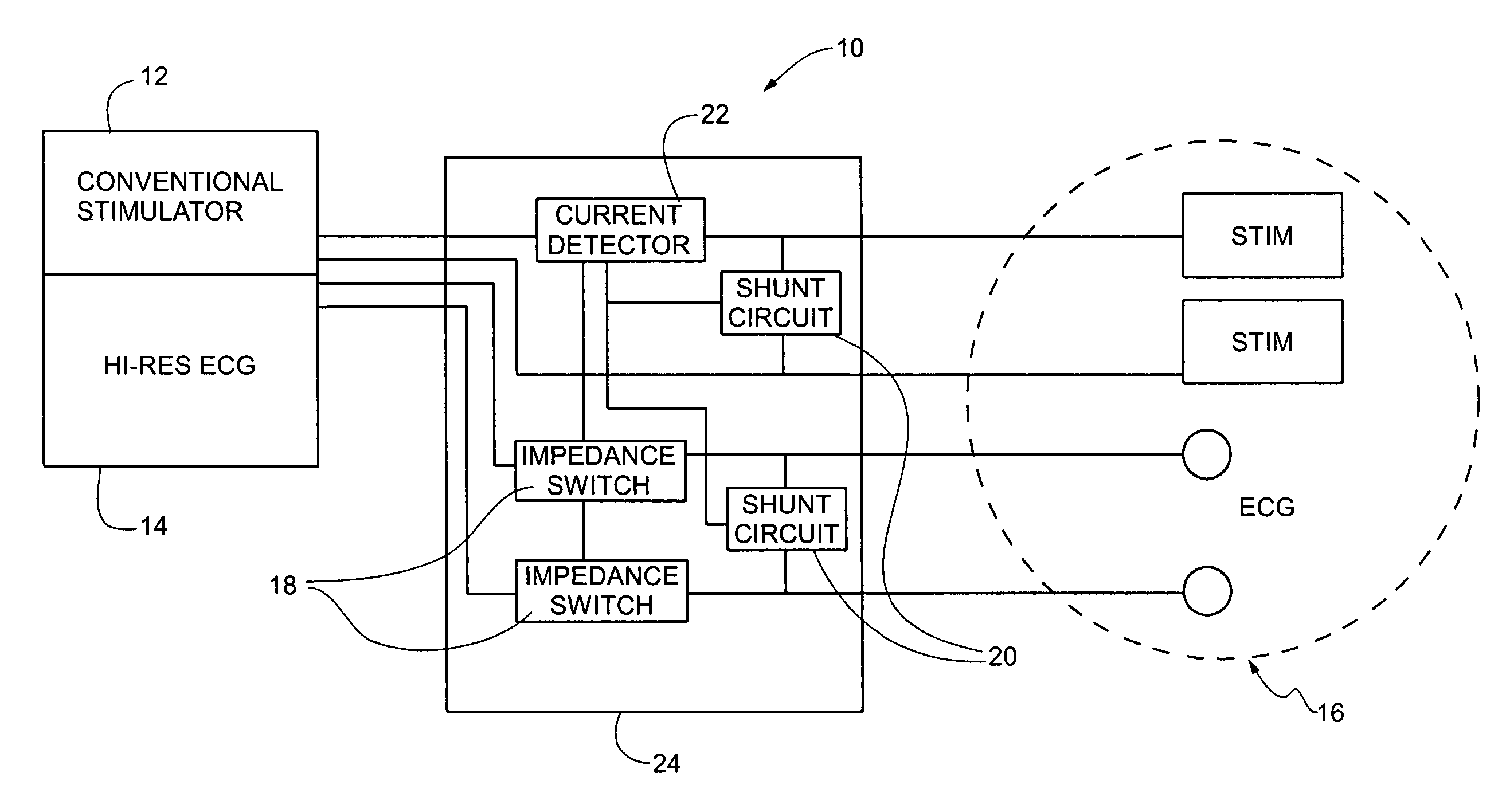
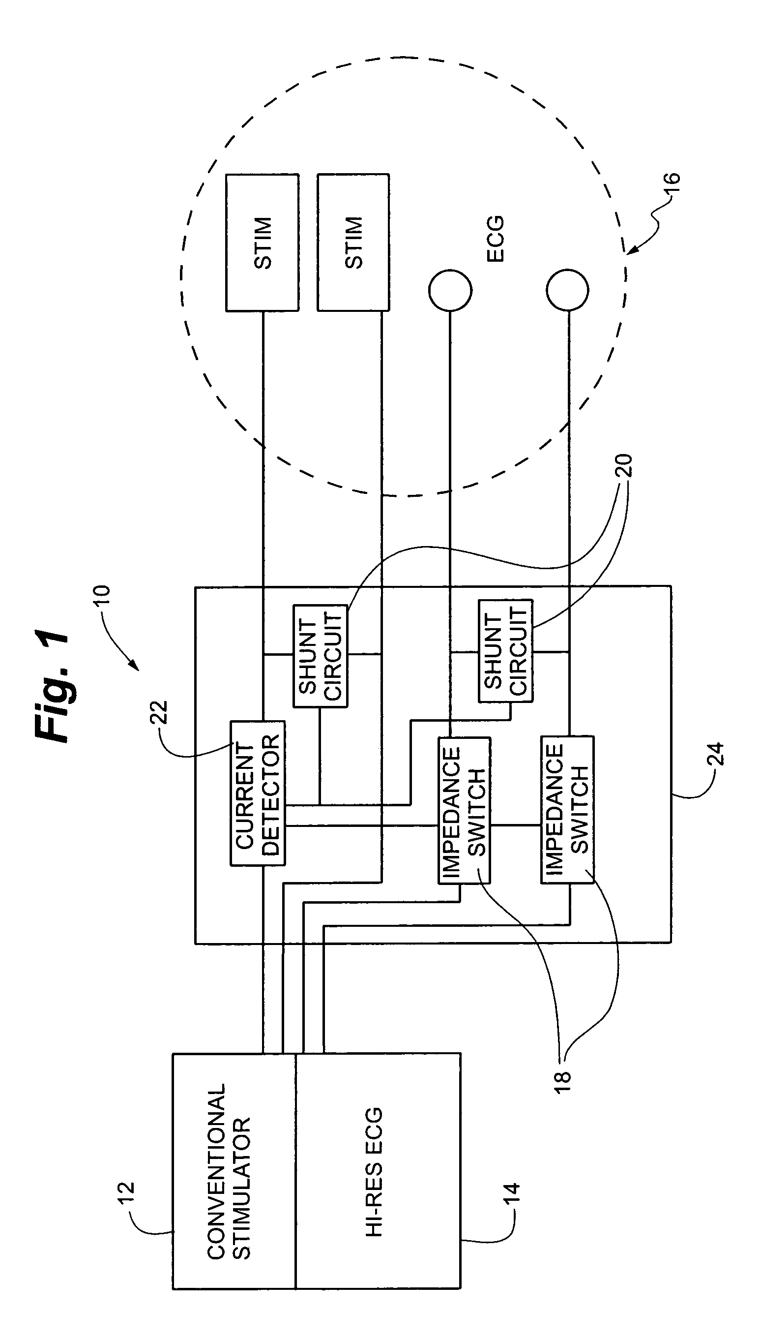
[0024]Referring to FIG. 1, the sensing artifact reduction module 10 of the present invention is shown interposed between a conventional stimulator 12, an electrocardiogram (ECG) 14 and electrodes 16. Referring to FIGS. 1, 2 and 3, ECG 14 may include a conventional ECG, a high resolution ECG, a vector ECG system or other like systems. Conventional stimulators 12 are known in the cardiac stimulating and sensing arts.

[0025]Sensing artifact reduction module 10 generally includes impedance switches 18, shunt circuits 20, current detector 22 and housing 24.

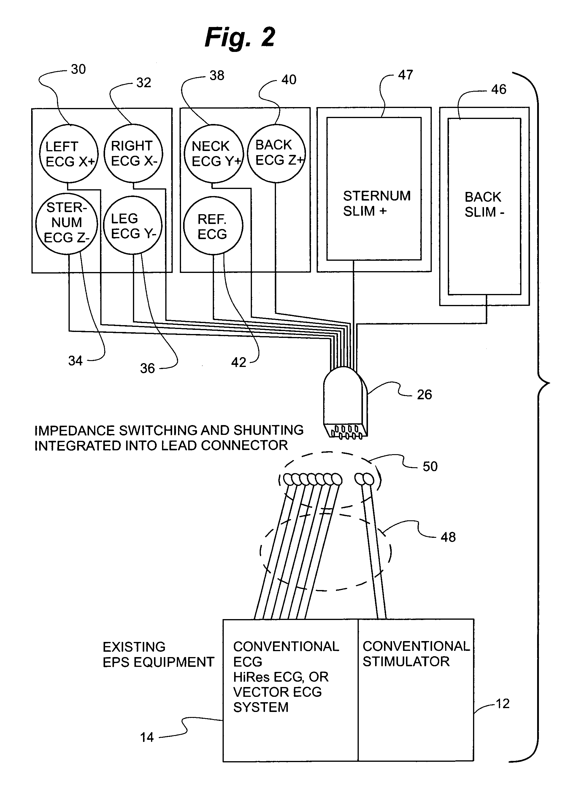
[0026]Referring to FIG. 2, the sensing artifact reduction module 10 is depicted as integrated into lead connector 26. Lead connector 26 is connected to electrodes 16 via a plurality of leads 28. Electrodes 16 include left ECG X positive electrode 30, right ECG X negative electrode 32, sternum ECG Z negative electrode 34, leg ECG Y negative electrode 36, neck ECG Y positive electrode 38, back ECG Z positive electrode 40, reference ECG el...


PUM


Abstract

Sensing artifacts in cardiac signals picked up by electrical leads are reduced by placing an electrical shunting switch across the conductors of the ECG sensing leads and the stimulation leads that deliver a subthreshold electrical stimulation. In addition, impedance switches are placed in series with the sensing leads. The shunting switches and impedance switches are then manipulated to present cardiac signals that can be analyzed for diagnostic purposes within less than 100 ms from delivery of a subthreshold electrical stimulation.

Description

RELATED APPLICATION[0001]The present application claims priority to U.S. Provisional Application No. 60 / 392,491 filed Jun. 28, 2002, which is incorporated herein in its entirety by reference.FIELD OF INVENTION[0002]The invention relates to the detection of patients' susceptibility to cardiac arrhythmias. More particularly, the present invention relates to methods and apparatus for improving the quality of cardiac signals detected for diagnostic purposes.BACKGROUND OF THE INVENTION[0003]Electrical sensing of cardiac signals is widespread and common in the diagnosis and treatment of cardiac disease. Cardiac signals are sensed in the form of ElectroCardioGrams (ECG) for diagnostic and monitoring purposes by devices such as conventional ECG strip chart recorders, signal averaged ECG monitors, Holter monitors, vector cardiographs, and a variety of similar devices. Cardiac signals are also sensed by most cardiac stimulation devices that apply electrical energy to the heart for therapeutic...

Claims


Application Information

Patent Timeline
Patent Type & Authority Patents(United States)
IPC IPC(8): A61N1/365A61B5/308A61N1/362
CPCA61B5/7217A61B5/0428A61B5/30A61B5/308A61B5/304
Inventor RYAN, STEPHEN J.HOIUM, HAROLD H.
Owner HARBINGER MEDICAL
Why Eureka
Try Eureka