Switching device for a battery, and battery comprising said switching device

a switching device and battery technology, applied in the direction of battery/fuel cell control arrangement, cell components, battery/resonant battery, etc., can solve the problems of tripping acoustic signal not being able to overlap with other wireless applications, affecting the spectrum of resonant signal, and reliably destroying container by acoustic resonance

Active Publication Date: 2017-01-12
ROBERT BOSCH GMBH
View PDF4 Cites 1 Cited by
  • Summary
  • Abstract
  • Description
  • Claims
  • Application Information

AI Technical Summary

Benefits of technology

[0011]The switching device according to the invention provides, for a battery of an electric vehicle or of a hybrid vehicle, an additional interrupter switch, in addition to a circuit breaker which is usually already provided and can be electrically operated, for interrupting a power line between a battery and a current collector of the vehicle. However, said additional emergency switch does not use the 12 V battery of the vehicle which is at risk of failure in the event of an accident, but rather operates independently of the vehicle current or independently of the 12 V battery of the vehicle. As a result, interruption of the power line in the event of an accident can be ensured if the circuit breaker which can be electrically operated fails, so that first responders, rescue service personnel or else the occupants themselves are protected against electric shocks due to damage to the power line between the battery and the current collector.

Problems solved by technology

As a result, the container can be reliably destroyed by the acoustic resonance effect.
Furthermore, the resonant frequency likewise has to be carefully selected, so that it is not possible for the tripping acoustic signal to overlap with other wireless applications or else other wireless applications to trigger the resonance effect in the container.
However, the spectrum of the resonant signal has to be limited in each case, so that the effective range between the emergency switch, which is formed by the switching device, and the acoustic signal transmitter is given by the output power of the signal transmitter, for example at 0.5 meter or less.

Method used


Image

  • Switching device for a battery, and battery comprising said switching device
  • Switching device for a battery, and battery comprising said switching device
  • Switching device for a battery, and battery comprising said switching device

Examples


Embodiment Construction

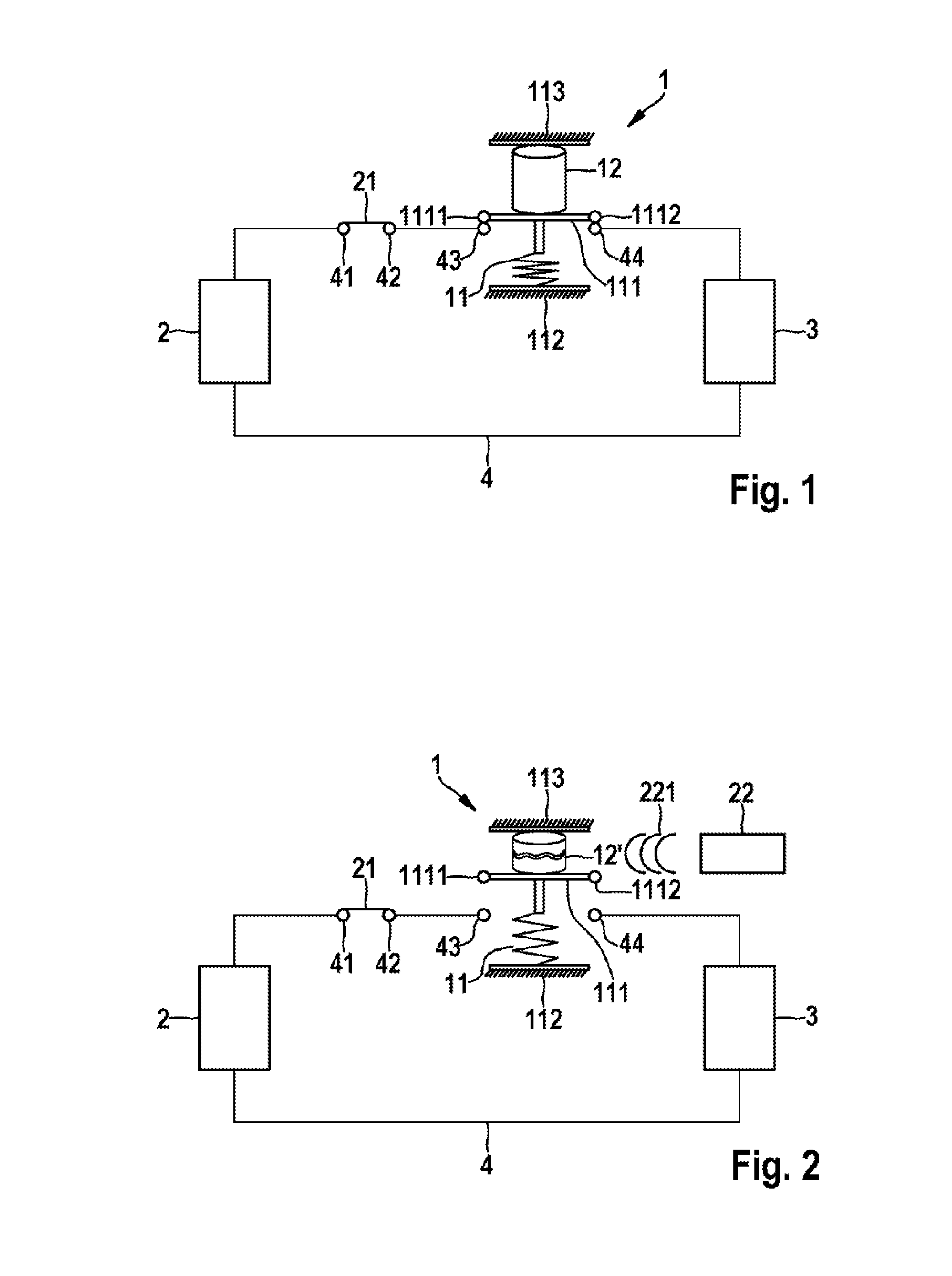
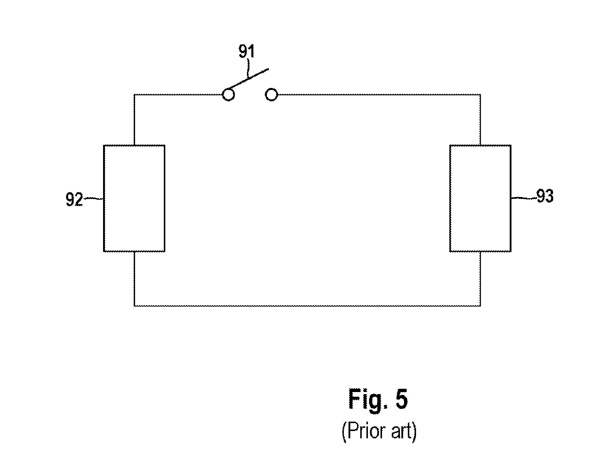
[0017]FIGS. 1 and 2 show a preferred embodiment of the switching device 1 according to the invention which, based on the prior art shown in FIG. 5, is arranged in a power line 4 between a battery 2 and an electric motor 3, which acts as a power collector, of an electric vehicle or hybrid vehicle connected in series with a circuit breaker 21 which can be electrically operated. Although the circuit breaker 21 is illustrated as being situated outside the battery 2 in FIGS. 1 and 2, it is preferably an integral constituent part of the battery 2. The circuit breaker 21 is supplied with power by a 12 V battery (not shown) of the vehicle. The switching device 1, which is shown in a closed state in FIG. 1, in which the power line 4 between the battery 2 and the electric motor 3 is closed, is similar to the circuit breaker 21 as is illustrated as being situated outside the battery 2, but is likewise preferably an integral constituent part of the battery 2. In the closed state, the circuit br...


PUM

PropertyMeasurementUnit
voltagesaaaaaaaaaa
currentsaaaaaaaaaa
acoustic resonanceaaaaaaaaaa

Abstract

The present invention relates to a switching device 1 for a battery 2, the switching device 1 being activated by an acoustic resonance effect to interrupt an electric line of the battery 2 to the outside. The present invention further relates to a battery 2 having an electrically activated power switch 21 for interruption of an electric line of the battery 2 to the outside and at least one such switching device 1, the power switch 21 and the switching device 1 being connected in series.

Description

BACKGROUND OF THE INVENTION[0001]Hybrid concepts or purely electrical drive concepts which are employed in road transport as purely electric vehicles or as hybrid vehicles, have increasingly been developed for some time in order to reduce the emissions by motor vehicles which are driven by internal combustion engines. The operation of electrical machines which are required for this purpose in motor and generator mode requires a corresponding electrical energy store in the respective vehicle, wherein, specifically in the case of electrically driven vehicles, voltages of several hundred volts are often required and a battery which is used as the energy store has to provide powers of up to several hundred kilowatts in the process. Examples of batteries of this kind include, inter alia, combinations of individual rechargeable battery cells, called a traction battery, which, for reasons of a high degree of efficiency and a high storage capacity, have high voltage potentials which could c...

Claims


Application Information

Patent Timeline
Patent Type & Authority Applications(United States)
IPC IPC(8): H01M2/34B60R16/033B60L1/00H01M2/10H01M10/48H01M50/222H01M50/572
CPCH01M2/34H01M2/1077H01M10/48H01M2200/00B60L1/00B60R16/033H01M2220/20H01M10/488H01M50/572H01M50/222B60L3/04Y02T90/40Y02T10/70Y02E60/10B60L58/10B60L3/0092B60L2240/54B60Y2200/91B60Y2200/92B60L3/0046B60L50/70B60L3/00
Inventor CHEN, CHEN
Owner ROBERT BOSCH GMBH
Why Eureka
Try Eureka