Communication device

a communication device and isotropic radiation technology, applied in the direction of antenna earthings, etc., can solve problems affecting the whole communication quality of the device, and achieve the effects of improving the impedance matching of the antenna element, enhancing the symmetry of the antenna element arrangement, and increasing the effective resonant length of the ground elemen

Active Publication Date: 2017-01-12
QUANTA COMPUTER INC
View PDF7 Cites 1 Cited by
  • Summary
  • Abstract
  • Description
  • Claims
  • Application Information

AI Technical Summary

Benefits of technology

[0008]The invention proposes a novel radiation mechanism for appropriately guiding currents on the system ground plane, so as to change the total radiation pattern of the communication device. Without adjusting the antenna element, the invention adds a current guide line for affecting the current distribution on the system ground plane, such that the surface currents are uniformly distributed on the system ground plane and some current nulls are eliminated. The current guide line enhances the symmetry of the antenna element arranged in the communication device, and therefore the communication device can achieve an isotropic radiation pattern.
[0009]In some embodiments of the invention, the metal guide line is coupled to the ground element. The length of the metal guide line is at least 0.2 times the length of the ground element. The metal guide line increases the effective resonant length of the ground element, and therefore a resonant mode of the antenna element is excited well. The impedance matching of the antenna element is also improved. According to the practical measurements, the metal guide line does not reduce the operation bandwidth of the antenna element. It should also be noted that when the total length of the metal guide line and the ground element is an integer multiple of 0.25 wavelength of a central operation frequency of the antenna element, the metal guide line can attract more surface currents on the system ground plane. As a result, the distribution of surface currents becomes more uniform, thereby improving the radiation pattern of the antenna element. In other words, the metal guide line is configured to remove the radiation nulls of the antenna element, resulting in an isotropic radiation pattern of the antenna element.

Problems solved by technology

Nevertheless, since embedded antennas are often disposed at a corner or at fragmented regions of a wireless access point due to its appearance or mechanism, the radiation pattern of the corresponding antenna tends to generate irregular concaves (i.e., radiation nulls), thereby affecting the whole communication quality of the devices.
As a result, it has become a critical challenge for antenna designers to design an isotropic antenna in the limited space of a wireless access point.

Method used


Image

  • Communication device
  • Communication device
  • Communication device

Examples


first embodiment

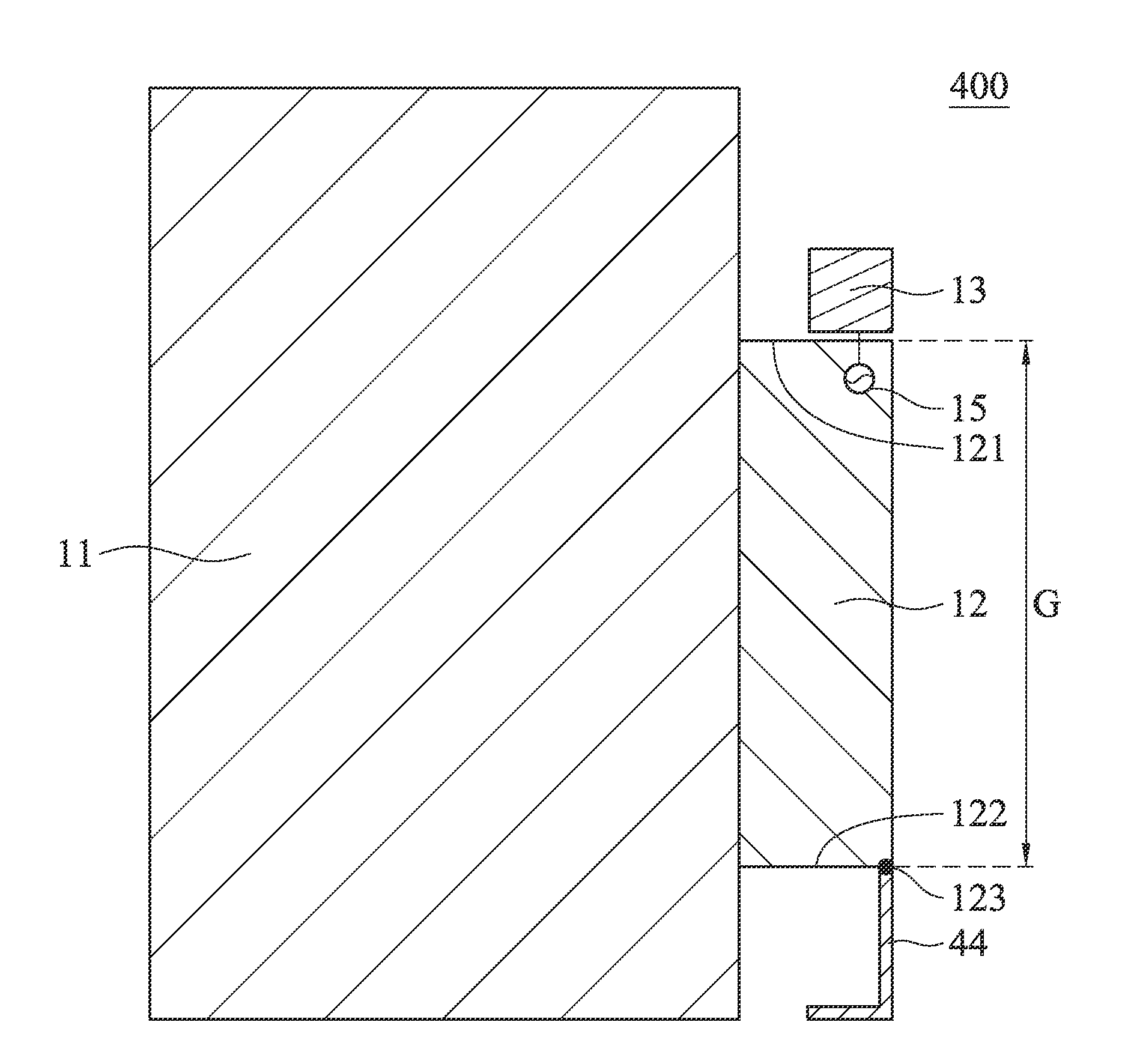
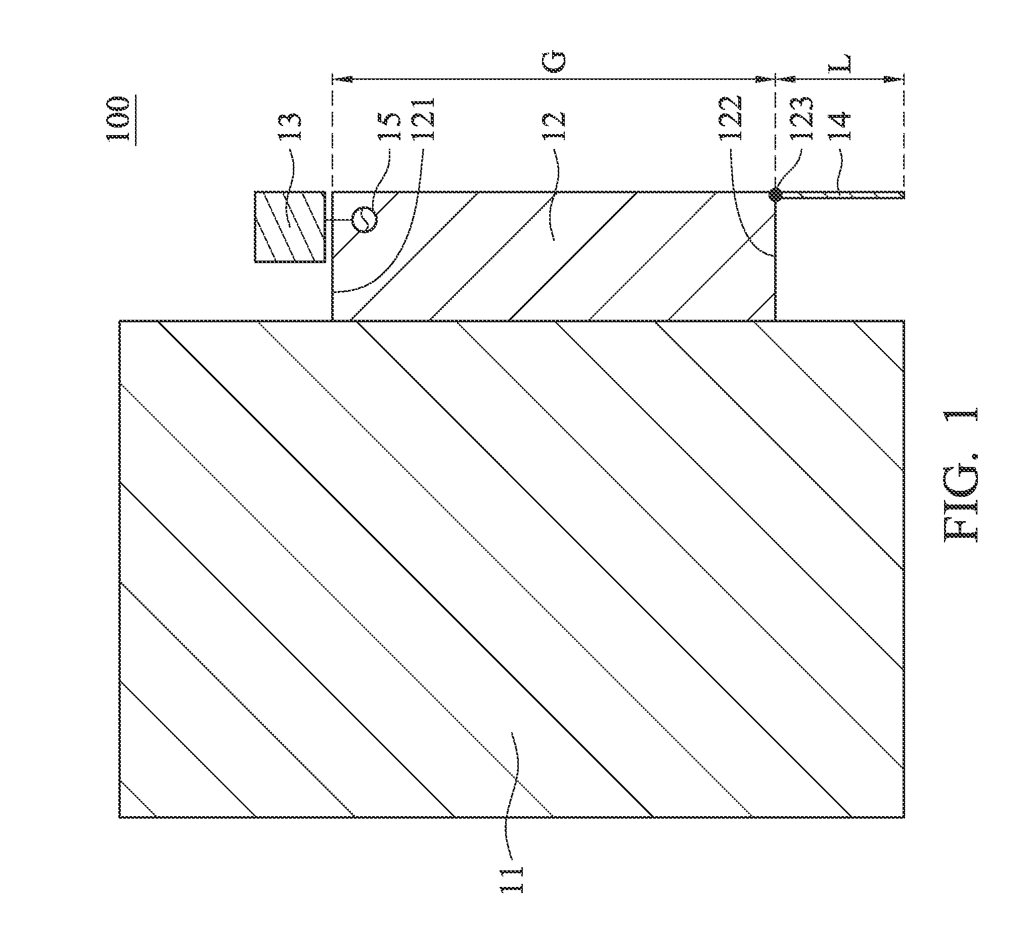
[0020]FIG. 1 is a diagram of a communication device 100 according to the invention. The communication device 100 may be a wireless access point. As shown in FIG. 1, the communication device 100 at least includes a system ground plane 11, a ground element 12, an antenna element 13, and a metal guide line 14. The system ground plane 11, the ground element 12, and the antenna element 13 may be made of conductive materials, such as copper, silver, aluminum, iron, or their alloys. The ground element 12 may be coupled to the system ground plane 11, or may be formed by an extension portion of the system ground plane 11. A combination of the ground element 12 and the system ground plane 11 may substantially have an inverted T-shape. The ground element 12 has a first edge 121, a second edge 122, and a connection point 123. The first edge 121 and the second edge 122 are opposite to each other. The antenna element 13 is disposed adjacent to, or at, the first edge 121 of the ground element 12. ...

fourth embodiment

[0025]FIG. 6 is a diagram of the antenna element 13 according to the invention. The antenna element 13 is a planar antenna. Specifically, the antenna element 13 is a coupled-fed loop antenna. The antenna element 13 includes a feeding radiation element 131 and a grounding radiation element 132. The feeding radiation element 131 is completely separate from the grounding radiation element 132, and a coupling gap is formed therebetween, such that feeding energy is delivered from the feeding radiation element 131 to the grounding radiation element 132. For example, the width of the coupling gap is shorter than 2 mm. The feeding radiation element 131 substantially has an inverted L-shape. One end of the feeding radiation element 131 is coupled to the signal source 15, and another end of the feeding radiation element 131 is open. The grounding radiation element 132 substantially has an inverted Y-shape. One end of the grounding radiation element 132 is coupled to a ground voltage VSS. The ...


PUM


Abstract

A communication device includes a system ground plane, a ground element, an antenna element, and a metal guide line. The ground element is coupled to the system ground plane. The ground element has a first edge, a second edge, and a connection point.
The first edge and the second edge are opposite to each other. The connection point is positioned at the second edge. The antenna element is disposed adjacent to, or at, the first edge. One end of the metal guide line is coupled to the connection point, and another end of the metal guide line is open.

Description

CROSS REFERENCE TO RELATED APPLICATIONS[0001]This Application claims priority of Taiwan Patent Application No. 104122256 filed on Jul. 9, 2015, the entirety of which is incorporated by reference herein.BACKGROUND OF THE INVENTION[0002]Field of the Invention[0003]The disclosure generally relates to a communication device, and more specifically, to a communication device with an isotropic radiation pattern.[0004]Description of the Related Art[0005]With the progress of mobile communication technology, there are more and diverse applications for wireless communication products. Wireless access points play an important role due to the development of smart houses and the Internet of things. In order to meet market trends and consumer demand, the design of a wireless access point needs a lightweight and stylish appearance. In such a situation, embedded antennas are the first choice. Nevertheless, since embedded antennas are often disposed at a corner or at fragmented regions of a wireless ...

Claims


Application Information

Patent Timeline
Patent Type & Authority Applications(United States)
IPC IPC(8): H01Q1/48
CPCH01Q1/48
Inventor HSU, HUNG-RENLIN, CHUN-ILIN, HUEI
Owner QUANTA COMPUTER INC
Why Eureka
Try Eureka