Eureka AIR delivers breakthrough ideas for toughest innovation challenges, trusted by R&D personnel around the world.

Optical pairing

a technology of optical pairing and pairing, applied in the field of data transfer, can solve the problem of not being able to be intercepted as easily, and achieve the effect of a higher degree of security

Inactive Publication Date: 2017-01-12
SOLPAD INC
View PDF3 Cites 10 Cited by
  • Summary
  • Abstract
  • Description
  • Claims
  • Application Information

AI Technical Summary

Benefits of technology

This patent introduces a solution to the limitations of conventional systems by using optical signals for communication. Optical signals are transmitted and received in a direct line-of-sight, making them more secure than traditional RF signals that can pass through walls. By using optical pairing, a would-be attacker would have to physically be present in the same room as the devices to be paired and have line-of-sight access to the optical signals. This higher degree of security ensures a safer communication method.

Problems solved by technology

Optical signals are transmitted and received in a line-of-sight fashion, and cannot be intercepted as easily as (RF) electromagnetic signals, for example, that may transmit through walls.

Method used

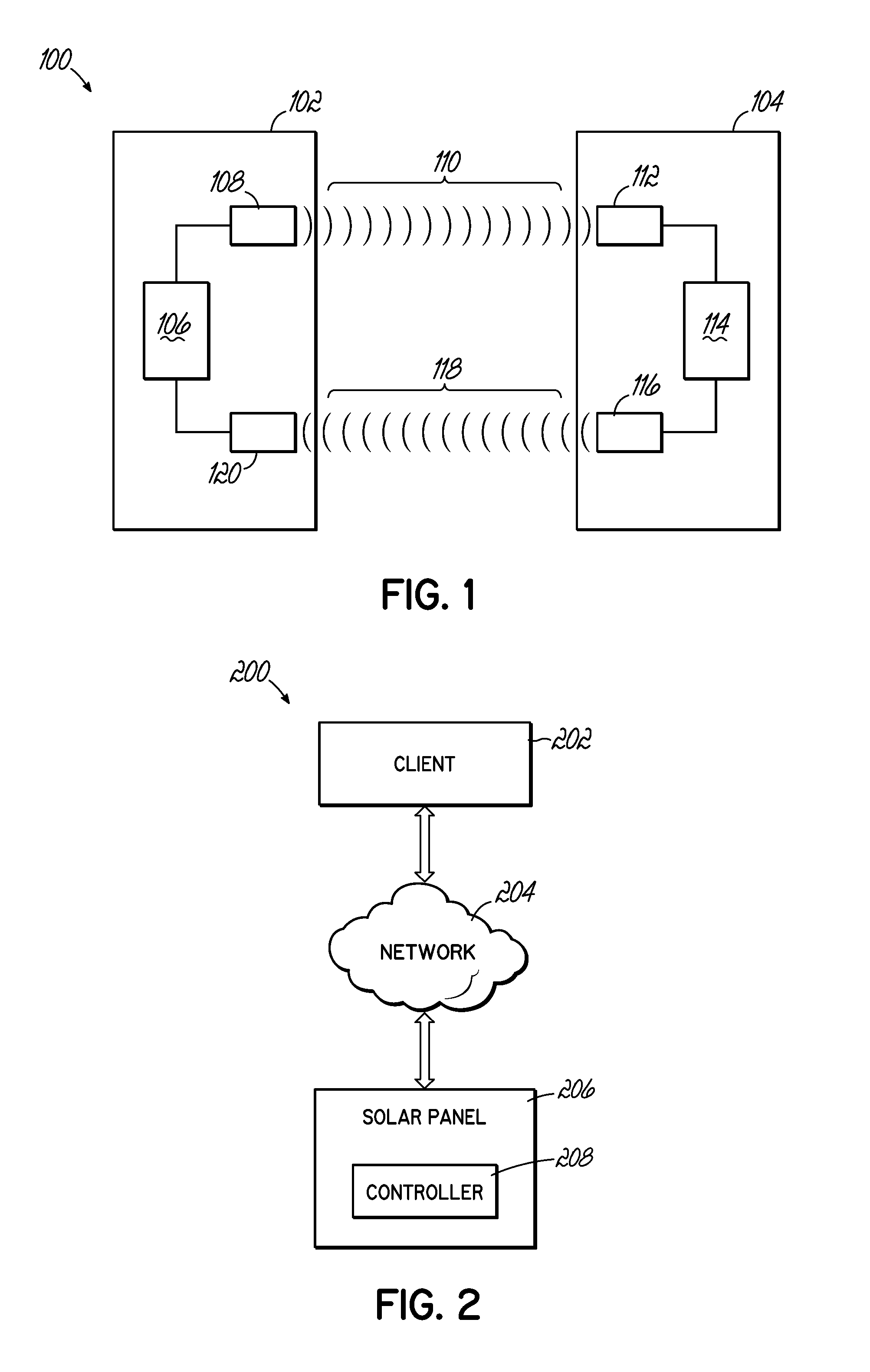
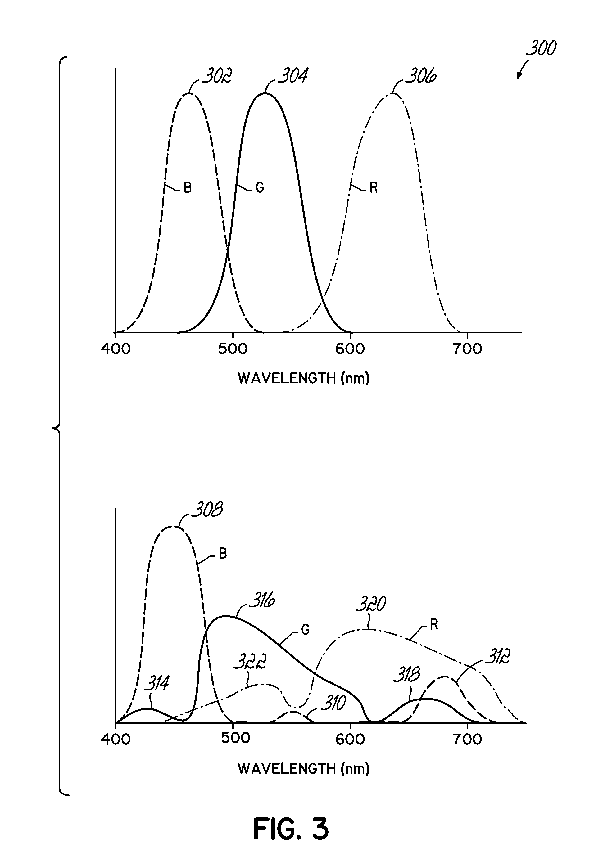

Image

  • Optical pairing
  • Optical pairing
  • Optical pairing

Examples


Embodiment Construction

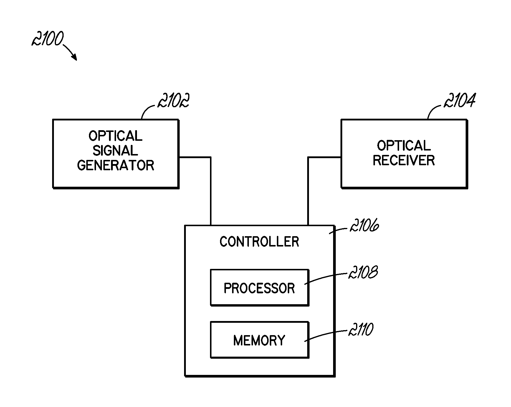
[0042]This disclosure provides systems and methods that transmit and receive data encoded as optical signals.

[0043]Reference in this specification to “one embodiment,”“an embodiment,” an “example embodiment,” etc., indicate that the embodiment described may include a particular feature, structure, or characteristic, but not every embodiment may necessarily include the particular feature, structure, or characteristic. Moreover, such phrases are not necessarily referring to the same embodiment. Further, when a particular feature, structure, or characteristic may be described in connection with an embodiment, it may be submitted that it may be within the knowledge of one of ordinary skill in the relevant art to affect such feature, structure, or characteristic in connection with other embodiments whether or not explicitly described.

[0044]The following detailed description refers to the accompanying drawings that illustrate exemplary embodiments. Other embodiments are possible, and modi...


PUM


Abstract

Disclosed systems and methods transmit and receive data encoded as optical signals that include a progression of symbols, with each symbol represented as a combination of light frequencies. Light is used as the carrier medium to limit reception to devices that are within visible range of the transmitting device. No mapping of data to symbols is required for generation of the symbol progression by the transmitter and no mapping of symbols to data for recognition of the symbols is required by the receiver. Disclosed embodiments allow arbitrary selection among a plurality of mappings between symbols sent and symbols received. Embodiments are robust to: ambient lighting conditions, differences in optical and temporal response of the first and second devices, and differences in relative orientation between the first and second devices. Embodiments enable a variety of functions including device discovery, feature discovery, beacon identification, status reporting, error readout, key exchange, and authentication.

Description

CROSS-REFERENCE TO RELATED APPLICATIONS[0001]This application claims benefit of co-pending U.S. patent application Ser. No. 15 / 260,477 filed Sep. 9, 2016 which is a continuation application of U.S. patent application Ser. No. 13 / 843,573 filed Mar. 15, 2013 and issued as U.S. Pat. No. 9,444,397 on Sep. 13, 2016, and claims the benefit of U.S. Provisional Patent Appl. No. 61 / 719,140, filed Oct. 26, 2012, which is incorporated herein by reference in its entirety.FIELD OF THE INVENTION[0002]The disclosed invention generally relates to data transfer between computing devices and in particular to transfer of data encoded as optical signals.BACKGROUND OF THE INVENTION[0003]Communication between two or more computing devices generally requires an initialization procedure. For example, in order for two devices to communicate using WiFi or Bluetooth™, a pairing operation must be performed. Generally the pairing operation is a process in which security credentials are transmitted from one devi...

Claims


Application Information

Patent Timeline
Patent Type & Authority Applications(United States)
IPC IPC(8): H04B10/54G08C23/04H04W12/06H04B10/114
CPCH04B10/541H04B10/1141H04B10/60H04W12/06G08C23/04H01L31/02021H02J3/46H02J9/06H02S40/38H02S40/30H02S40/36H02J2300/24H02J3/381Y02E10/56Y04S40/20Y02E70/30
Inventor ESTES, CHRISTOPHER A.URBAN, JEFFREY STUART
Owner SOLPAD INC
Why Eureka
Eureka Blog
Learn More