Header Tilt Mechanism

a header and tilting technology, applied in the field of harvesters, can solve the problems of general inability to properly balance the header, wavy stubble pattern, other problems, etc., and achieve the effect of less reaction forces, less transmission of excessive forces, and easy adjustment of the header til

Inactive Publication Date: 2017-01-19
CNH IND AMERICA LLC
View PDF0 Cites 16 Cited by
  • Summary
  • Abstract
  • Description
  • Claims
  • Application Information

AI Technical Summary

Benefits of technology

[0017]Sliding contact directly between the pitch plate at the front of the feeder housing and the face plate to which the header mounts is advantageously eliminated. As a result, the transmission of excessive forces is minimized between the header and the combine itself. In this way, the rolling movements of the combine do not perturb the header and vice versa, where the arrangement is not provided with tilt cylinders, and the tilt cylinders can more readily adjust the til

Problems solved by technology

This connection in conventional combines is generally unable to properly balance the header and suffers from the transmission of excessive forces from the face plate to the front of the feeder housing, and vice versa, due to friction at the sliding joints.
This can result in uncontrolled, sometimes oscillating movements of the header giving a wavy stubble pattern.
As header sizes and weights become greater, these and other problems exaggerate.
However, there is no elastic movement possible between the combine and the header.
Therefore, as the combine moves over uneven ground, combine movements are transmitted to the header, and magnified by the width of the header, resulting in the uneven stubble pattern mentioned.
This results in a significant reaction force that is largely absorbed by the combine tires, which flex so that the combine itself tilts slightly in the opposite direction.
Friction between the face plate and the feeder housing can cause these adjustments to be more jerky or abrupt, resulting in sharper reaction forces, and greater perturbation of the header and combine system.
Usually, simple polymer strips are provided in order to reduce friction, with limited effect.
Heavy headers and forceful forward motion causes

Method used


Image

  • Header Tilt Mechanism
  • Header Tilt Mechanism
  • Header Tilt Mechanism

Examples


Embodiment Construction

[0037]The terms “grain”, “straw” and “tailings” are used principally throughout this specification for convenience but it is to be understood that these terms are not intended to be limiting. Thus “grain” refers to that part of the crop material which is threshed and separated from the discardable part of the crop material, which is referred to as non-grain crop material, MOG or straw. Incompletely threshed crop material is referred to as “tailings”. Also the terms “forward”, “rearward”, “left” and “right”, when used in connection with the agricultural harvester and / or components thereof are usually determined with reference to the direction of forward operative travel of the harvester, but again, they should not be construed as limiting. The terms “longitudinal” and “transverse” are determined with reference to the fore-and-aft direction of the agricultural harvester and are equally not to be construed as limiting.

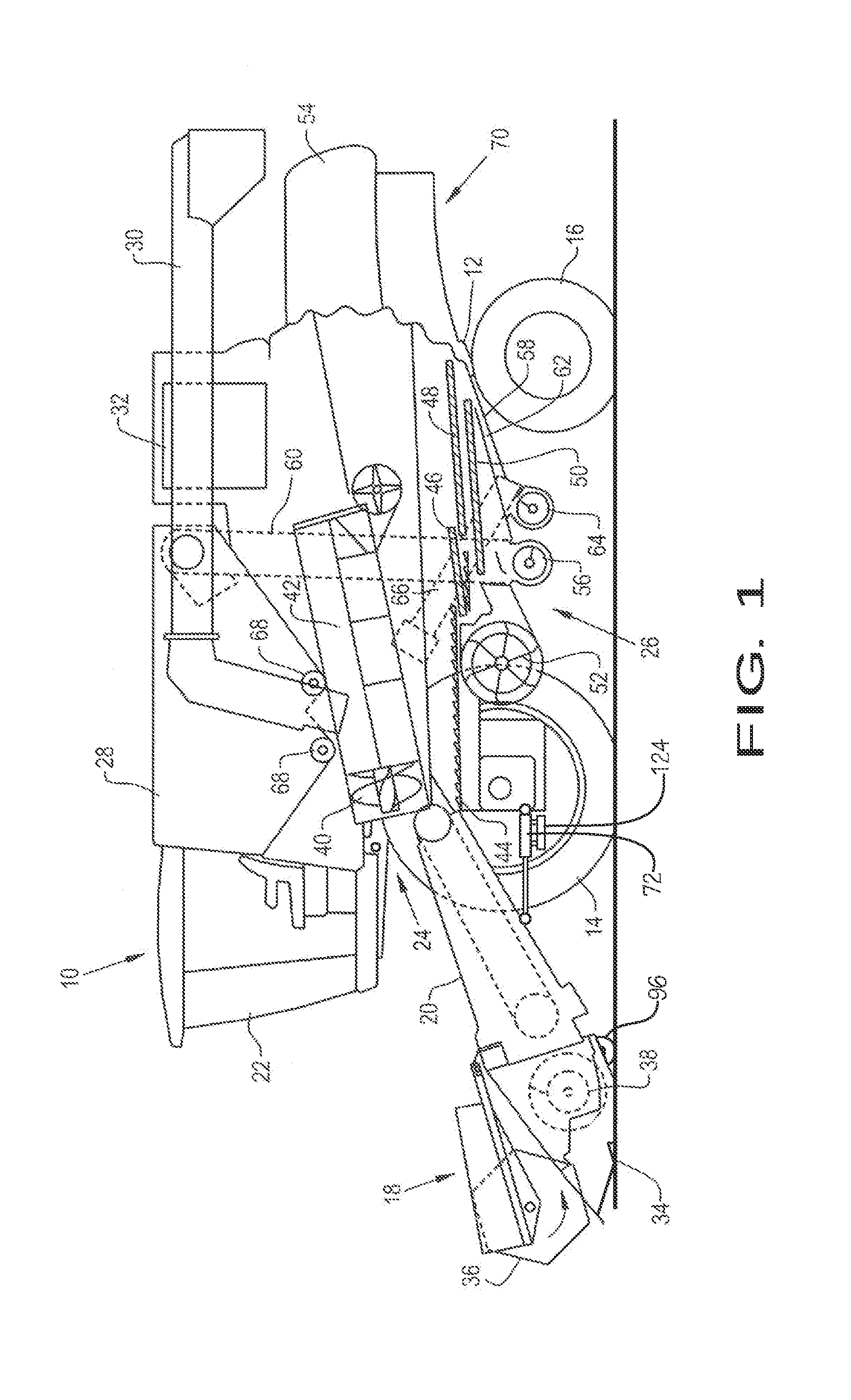
[0038]Referring now to the drawings, and more particularly to FIG. 1...


PUM


Abstract

An agricultural harvester including a chassis and a header for gathering a crop and feeding it into the agricultural harvester. The agricultural harvester further includes a threshing and separating system, a grain cleaning system for separating grain from MOG, and a feeder housing for moving the crop gathered by the header from the header into the threshing and separating system. The agricultural harvester further includes a header tilt mechanism that allows the header to tilt in order to follow ground contours. The header tilt mechanism may use a face plate movably attached to the feeder housing. The header tilt mechanism includes at least one straight line linkage movably connecting the header to the feeder housing. The feeder housing or header tilt mechanism may be provided with hydraulic cylinders or pressure controlling or limiting arrangements.

Description

CROSS REFERENCE TO RELATED APPLICATION[0001]This application claims priority to Belgium Application No. 2015 / 5447, filed Jul. 14, 2015, the contents of which are incorporated herein by reference.FIELD OF THE INVENTION[0002]The present invention relates to agricultural harvesters, and, more particularly, to the connection between the feeder housing and the header of agricultural harvesters.BACKGROUND OF THE INVENTION[0003]Combines are used to harvest agricultural crops such as corn, soybeans, wheat and other grain crops. As the combine is driven through crop fields, the combine cuts the crop, separates the desired crop from the undesired waste, stores the crop, and discards the waste.[0004]In a typical combine, a header is mounted to a face plate adjoining the feeder housing at the front of the combine to gather the crop and feed the crop into the combine for processing. As the combine is driven through the field, the crop material is collected by the header and deposited into a feed...

Claims


Application Information

Patent Timeline
IPC IPC(8): A01D41/14A01D75/28A01D61/00
CPCA01D41/145A01D75/287A01D61/008A01D41/16
Inventor BORRY, STIJNNAAKTGEBOREN, ADRIANUSVAN HAVER, RONALDTHEUNYNCK, VINCENTDEBAETS, PATRICK
Owner CNH IND AMERICA LLC
Why Eureka
Try Eureka