Surface Reinforced Concrete Masonry Units

a technology of reinforced concrete and masonry units, applied in the direction of walls, building components, constructions, etc., can solve the problems of reducing the design life of the structure, increasing the operation and maintenance costs, and reducing the durability, so as to reduce the self-weight of the wall, facilitate the bonding, and reduce the effect of material

Inactive Publication Date: 2017-01-19
UNIVERSITY OF MANITOBA
View PDF25 Cites 11 Cited by
  • Summary
  • Abstract
  • Description
  • Claims
  • Application Information

AI Technical Summary

Benefits of technology

[0021]The details and the general construction procedure for constructing a wall using SRCMU has also been modified from the traditional concrete block wall system. Grouting the cores are not required since there are no reinforcement in the cores; as noted earlier, grouting facilitates the bond between the reinforcement and the rest of the wall in conventional CMU construction. Elimination of grout will result in many benefits such as reduction of material (rendering the wall assembly and the concrete block wall cons...

Problems solved by technology

Cracking of a concrete block wall considerably reduces its durability and increases the operations and maintenance costs while al...

Method used


Image

  • Surface Reinforced Concrete Masonry Units
  • Surface Reinforced Concrete Masonry Units
  • Surface Reinforced Concrete Masonry Units

Examples


Embodiment Construction

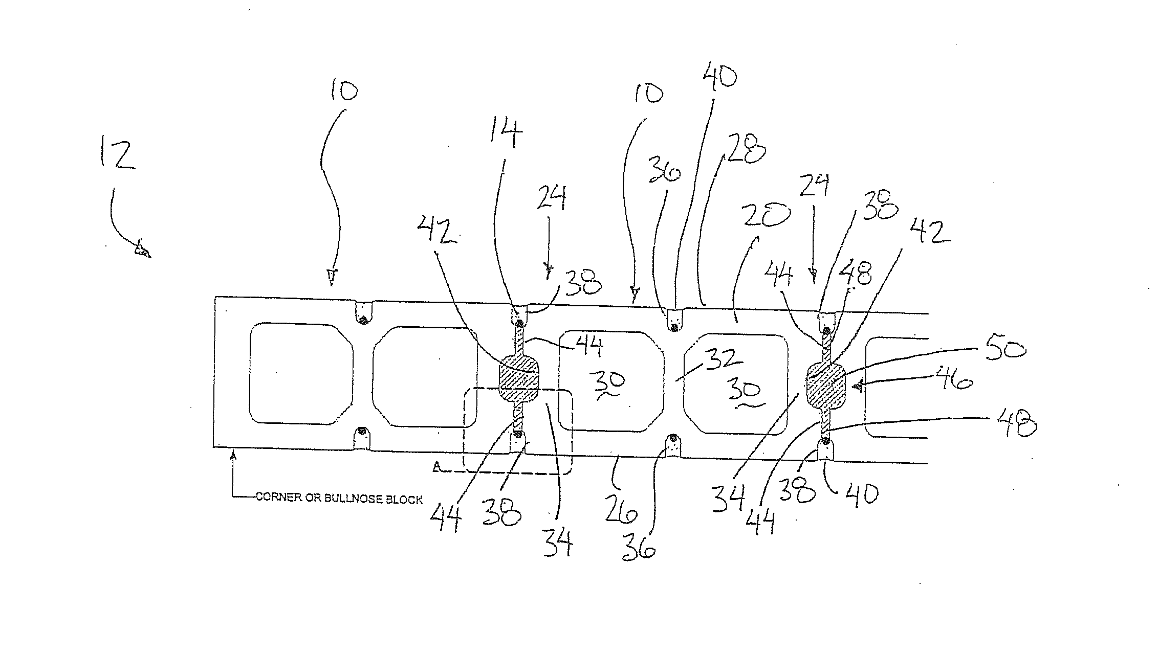
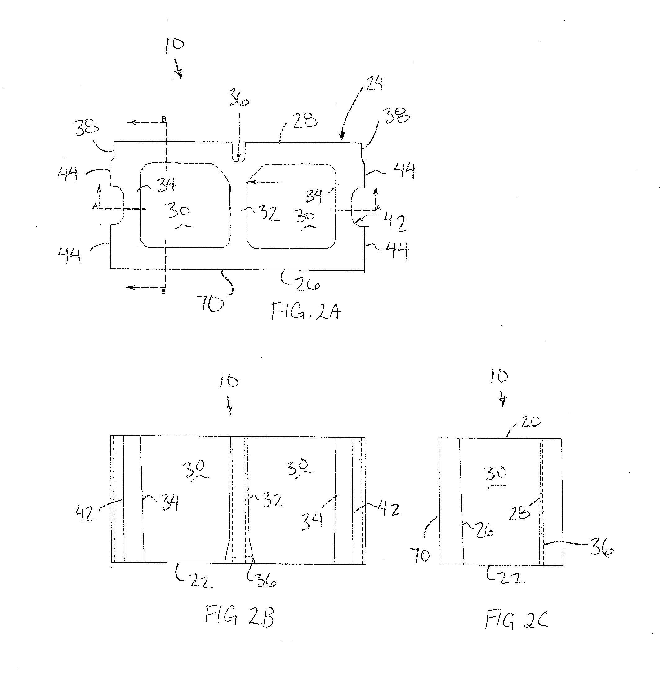
[0051]Referring to the accompanying figures, there is illustrated a masonry unit generally indicated by reference numeral 10. The masonry unit 10 is particularly suited for use in the construction of a masonry wall 12 as shown in FIGS. 4A through 4C. The masonry units 10 permit reinforcement members 14, for example conventional rebar or other forms of elongate reinforcement, to be recessed into one or both exterior surfaces of the assembled wall.

[0052]The wall 12 is typically constructed in a manner similar to the use of conventional concrete masonry units by abutting the units longitudinally end to end in rows with the rows being stacked one above the other. Each unit may be vertically aligned directly above a corresponding unit in the previous row therebelow, or more preferably each masonry unit 10 is offset longitudinally by half of the length of the unit relative to a corresponding unit of the previous row so that each masonry unit is engaged upon a portion of two additional mas...


PUM


Abstract

A masonry wall is formed of masonry block units abutted with one another in series within stacked rows. Each masonry block unit is a concrete body having two opposing exterior side walls defining respective portions of the assembly masonry wall. Vertical reinforcement channels are formed in the exterior side walls of each masonry block unit so as to be open laterally to the exterior. The reinforcement channels align with corresponding channels in the masonry block units in adjacent stacked rows to receive elongate reinforcement members, for example rebar, inserted laterally therein from the exterior surface of the assembly masonry wall. A bonding material can then be recessed laterally into the reinforcement channels so as to bond the reinforcement members to the masonry assembly.

Description

FIELD OF THE INVENTION[0001]The present invention relates to concrete masonry units for use with elongate reinforcement members in the construction of a masonry wall, and more particularly the present invention relates to concrete masonry units arranged to receive the reinforcement members recessed into the exterior sides of the units.BACKGROUND[0002]Existing Concrete Masonry Units (CMUs) have two hollow cores and are fabricated with two exterior flat surfaces. When constructing a wall using CMUs they are typically assembled by placing reinforcement and grout in the center of each core. The reinforcement is introduced into the assembly to enable the wall to resist tension stress while the grout is necessary to create a bond between the reinforcement and the concrete blocks. The reinforcement is placed near the centre axis of the block which is also the neutral axis on the wall as a flexural member. When the reinforcement in a flexural member is placed close to the neutral axis it do...

Claims


Application Information

Patent Timeline
IPC IPC(8): E04B2/16E04B2/20E04B2/24E04C1/00
CPCE04B2/16E04B2/24E04B2/20E04C1/00E04B2/48E04B2002/0213E04B2002/0282
Inventor HASHEMIAN, FARIBORZ KHALEGHI
Owner UNIVERSITY OF MANITOBA
Why Eureka
Try Eureka