
Laser speckle contrast imaging system, laser speckle contrast imaging method, and apparatus including the laser speckle contrast imaging system

a contrast imaging and laser speckle technology, applied in the field of laser speckle contrast imaging systems and laser speckle contrast imaging methods, can solve the problems of difficult application of general laser speckle contrast imaging to blood flow rate measurement, and noise within the resulting imaged contrast information

Active Publication Date: 2017-01-19
SAMSUNG ELECTRONICS CO LTD +1
View PDF5 Cites 25 Cited by
  • Summary
  • Abstract
  • Description
  • Claims
  • Application Information

AI Technical Summary

Benefits of technology

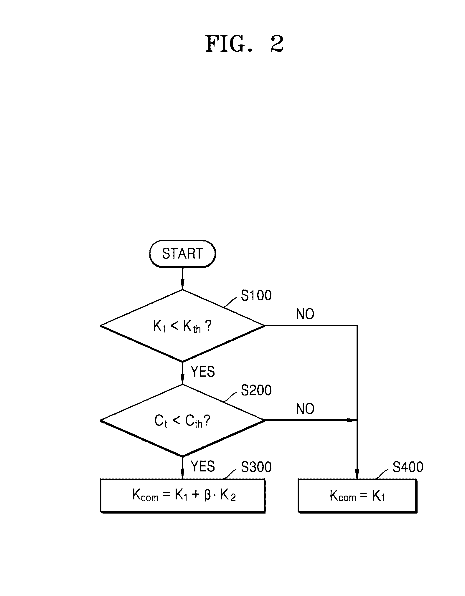
The patent text describes a system that can capture images of a person's face using a special device. The system can then process these images to extract information about the person's identity. The system uses a special technique called "speckle contrast imaging" to capture the images. This technique involves acquiring two different images of the person's face, one with and one without a background noise. The system then uses these two images to create a final image that is more accurate and free of noise. The system can also use a noise compensation algorithm to adjust the final image based on the correlation between the two original images. Overall, this technology can improve the accuracy and quality of facial recognition systems.

Problems solved by technology

Due to the limiting condition, when a target blood vessel or a spot through which a fluid flows, which is to be imaged, shakes or moves due to an external influence, noise exists within the resulting imaged contrast information.
Therefore, it is difficult to apply the general laser speckle contrast imaging to a blood flow rate measurement through imaging of the skin of a human body or an animal that is not anesthetized.

Method used


Image

  • Laser speckle contrast imaging system, laser speckle contrast imaging method, and apparatus including the laser speckle contrast imaging system
  • Laser speckle contrast imaging system, laser speckle contrast imaging method, and apparatus including the laser speckle contrast imaging system
  • Laser speckle contrast imaging system, laser speckle contrast imaging method, and apparatus including the laser speckle contrast imaging system

Examples


Embodiment Construction

[0039]Reference will now be made in detail to exemplary embodiments, examples of which are illustrated in the accompanying drawings, wherein like reference numerals refer to like elements throughout. In this regard, the present exemplary embodiments may have different forms and should not be construed as being limited to the descriptions set forth herein. Accordingly, the exemplary embodiments are merely described below, by referring to the figures, to explain aspects. The sizes of the elements may be exaggerated for clarity and convenience of description. The following exemplary embodiments are merely exemplary and various modifications may be made thereto.

[0040]It will be understood that when an element is referred to as being “disposed on” another element, it may be directly or indirectly disposed on the other element. In this aspect, for example, intervening elements may be present.

[0041]It will be understood that, although the terms “first”, “second”, etc. may be used herein to...


PUM


Abstract

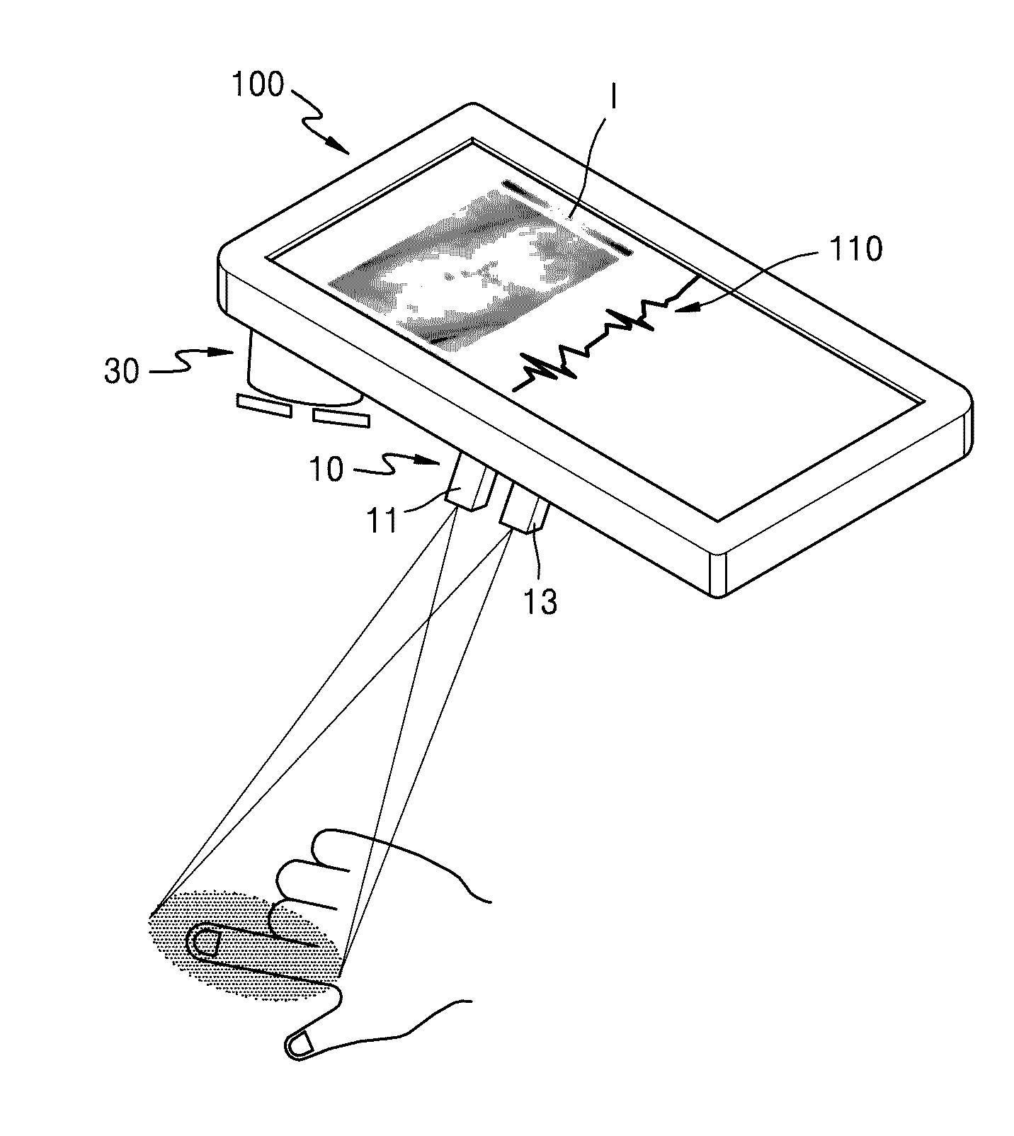
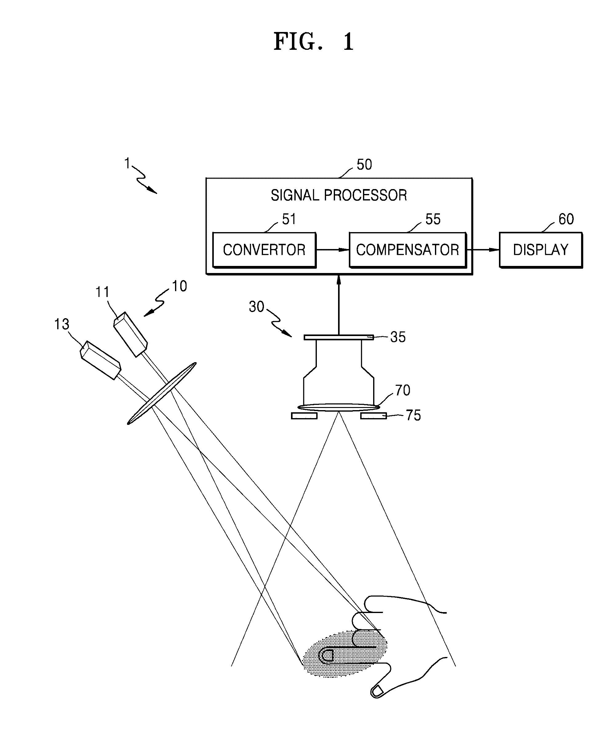
Provided are a laser speckle contrast imaging method, a laser speckle contrast imaging system, and an apparatus which includes the laser speckle contrast imaging system. The laser speckle contrast imaging system includes a laser light source configured to irradiate laser beams toward a subject, the laser beams having a plurality of wavelength bands and different surface transmittances with respect to the subject. An imaging unit is configured to acquire speckle images by capturing images of speckles by using an image sensor, the speckles being formed when the irradiated laser beams are scattered from the subject. A signal processor is configured to convert the acquired speckle images into speckle contrast images and to acquire a compensated speckle contrast image by compensating for a change caused by a movement of the subject.

Description

CROSS-REFERENCE TO RELATED APPLICATION[0001]This application claims priority from Korean Patent Application No. 10-2015-0100515, filed on Jul. 15, 2015, in the Korean Intellectual Property Office, the disclosure of which is incorporated herein by reference in its entirety.BACKGROUND[0002]1. Field[0003]Exemplary embodiments relate to laser speckle contrast imaging methods, laser speckle contrast imaging systems, and apparatuses including the laser speckle contrast imaging systems.[0004]2. Description of the Related Art[0005]Laser speckle contrast imaging is a technology for measuring or imaging a fine change or a flow rate of a target subject by using a laser light source which is capable of generating speckles. The laser speckle contrast imaging may generate speckles by using a light source having a single wavelength band, and may image the generated speckles by using one speckle-generating light source and one speckle imaging device. A flow rate at a target position may be recorded...

Claims


Application Information

Patent Timeline
Patent Type & Authority Applications(United States)
IPC IPC(8): G06K9/46G06T7/20G06T7/00A61B5/00G02B27/48G02B13/00A61B5/026G06K9/00G06T5/00
CPCG06K9/4661G06K9/00335G06T7/20G06T7/0012G06T5/00G06T2207/20172G02B13/009A61B5/0261A61B5/7207A61B5/742G06T2207/30104G02B27/48A61B5/6898G02B13/146G02B21/0008G06V40/1394G06V40/14
Inventor ROH, YOUNGGEUNLEE, BYOUNGHOYEOM, JIWOONJEONG, YOUNGMOJEONG, JINSOO
Owner SAMSUNG ELECTRONICS CO LTD
Learn More