
Unified RF Power Delivery Single Input, Multiple Output Control For Continuous And Pulse Mode Operation

a power delivery system and unified technology, applied in the field of radio frequency (rf) power delivery systems and centralized control of rf impedance matching networks, can solve the problems of increasing complexity, increasing complexity, and increasing complexity of conventional approach in connection with both continuous wave and pulse mode operation

Active Publication Date: 2017-01-19
MKS INSTR INC
View PDF0 Cites 32 Cited by
  • Summary
  • Abstract
  • Description
  • Claims
  • Application Information

AI Technical Summary

Benefits of technology

The patent describes a radio frequency (RF) control system that can adjust the power ratio between different RF output signals to control the distribution of power to different loads. This is achieved through a ratio tuning element in the matching network that receives a ratio control signal from a controller. The system can also adjust the pulse edge of a pulsed RF signal using an impedance tuning element controlled by a pulse edge control signal. The technical effects of this system include improved control over RF power distribution and improved timing accuracy for pulsed RF signals.

Problems solved by technology

As plasma systems have evolved, many new challenges exist to meet the specifications required to meet critical manufacturing specifications for both continuous wave and pulsed RF control.
Further, the transition from continuous wave RF power delivery systems to pulse RF power delivery systems presents additional challenges.
The conventional approach has various cost and complexity limitations in connection with both continuous wave and pulse mode operation.
The conventional approach also requires that the matching network includes computing resources to perform the ratio control functionality, also adding cost and complexity.

Method used


Image

  • Unified RF Power Delivery Single Input, Multiple Output Control For Continuous And Pulse Mode Operation
  • Unified RF Power Delivery Single Input, Multiple Output Control For Continuous And Pulse Mode Operation
  • Unified RF Power Delivery Single Input, Multiple Output Control For Continuous And Pulse Mode Operation

Examples


Embodiment Construction

[0033]Example embodiments will now be described more fully with reference to the accompanying drawings.

[0034]Example embodiments are provided so that this disclosure will be thorough, and will fully convey the scope to those who are skilled in the art. Numerous specific details are set forth such as examples of specific components, devices, and methods, to provide a thorough understanding of embodiments of the present disclosure. It will be apparent to those skilled in the art that specific details need not be employed, that example embodiments may be embodied in many different forms and that neither should be construed to limit the scope of the disclosure. In some example embodiments, well-known processes, well-known device structures, and well-known technologies are not described in detail.

[0035]The terminology used herein is for the purpose of describing particular example embodiments only and is not intended to be limiting. As used herein, the singular forms “a,”“an,” and “the” ...


PUM


Abstract

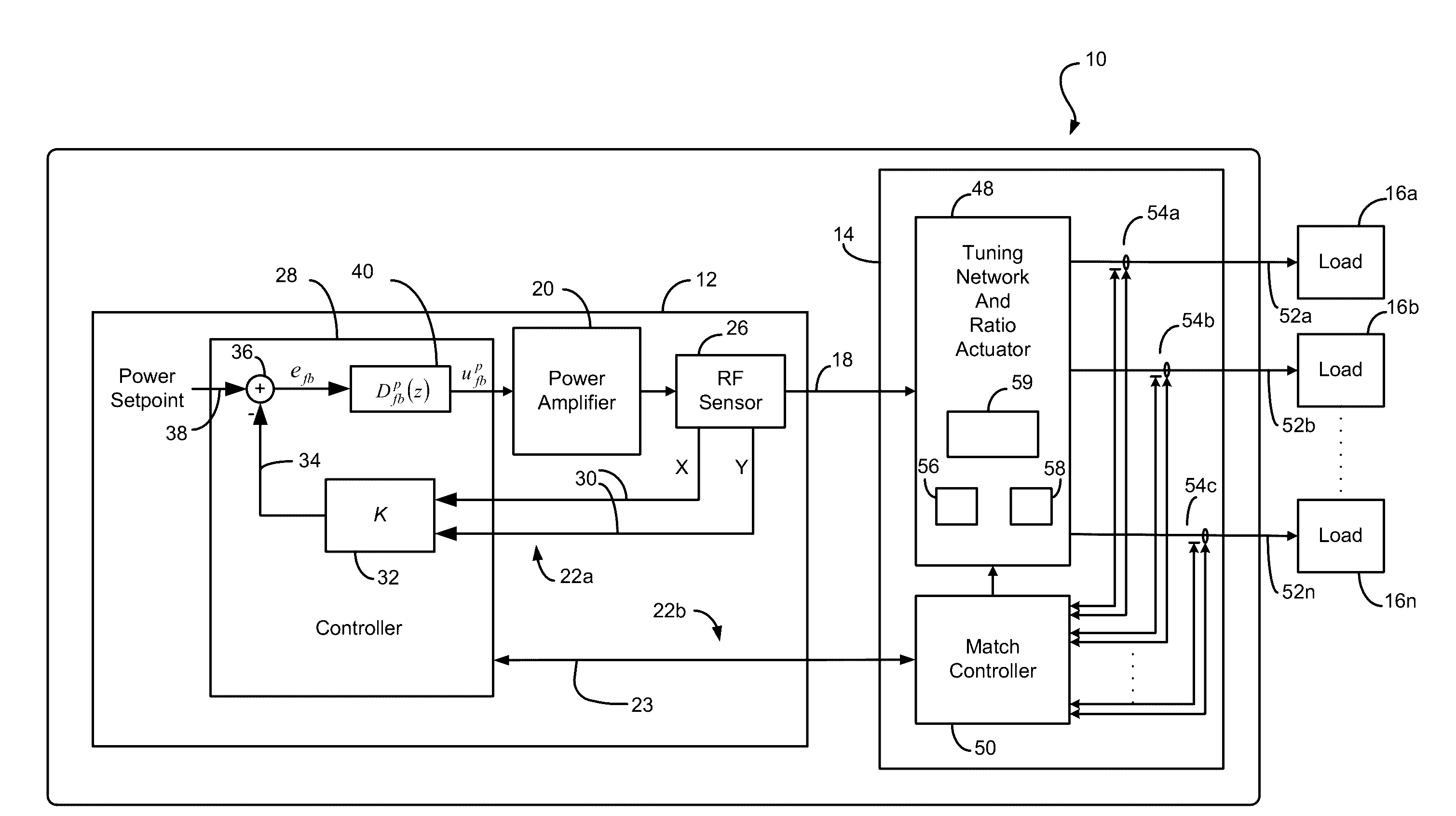
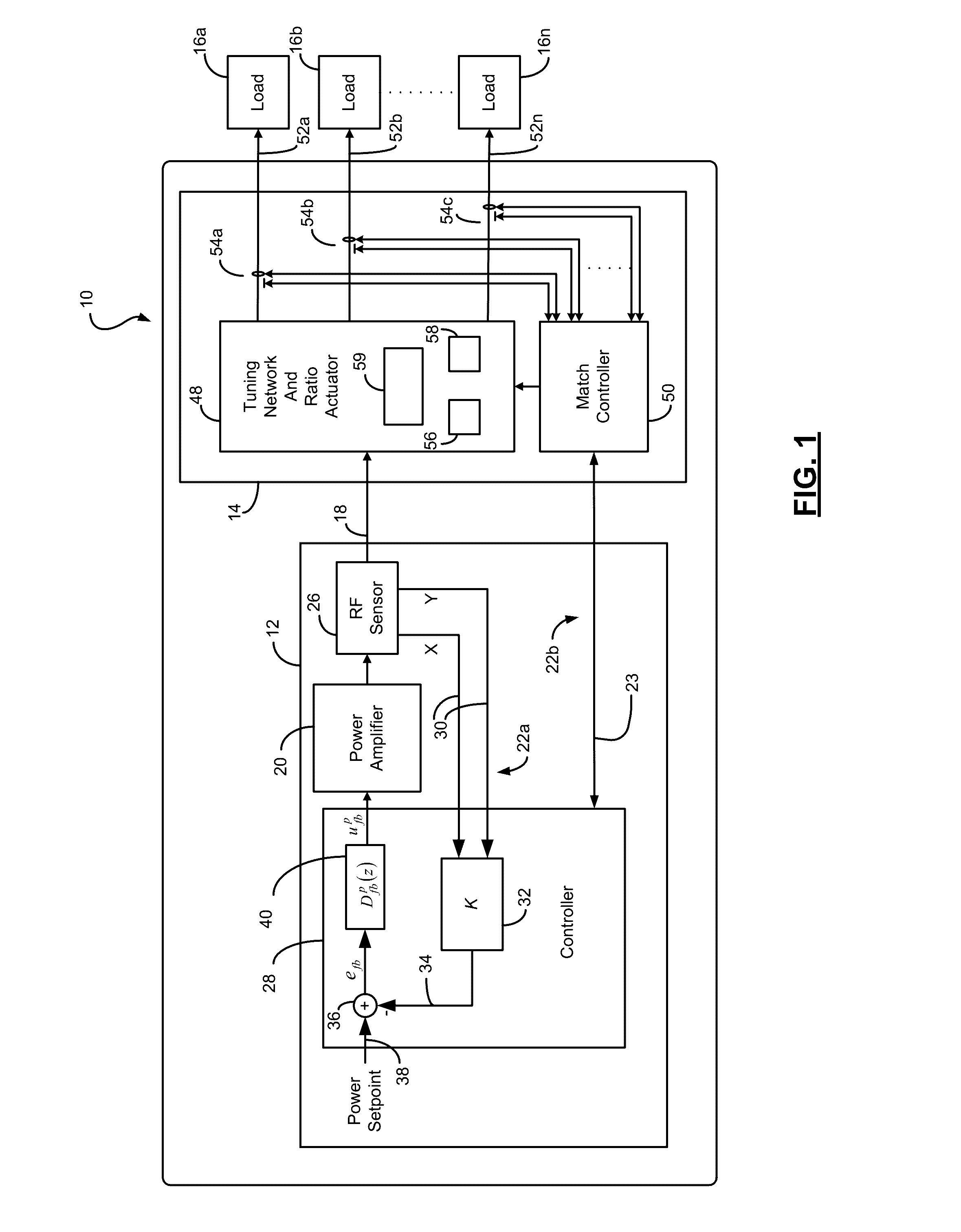
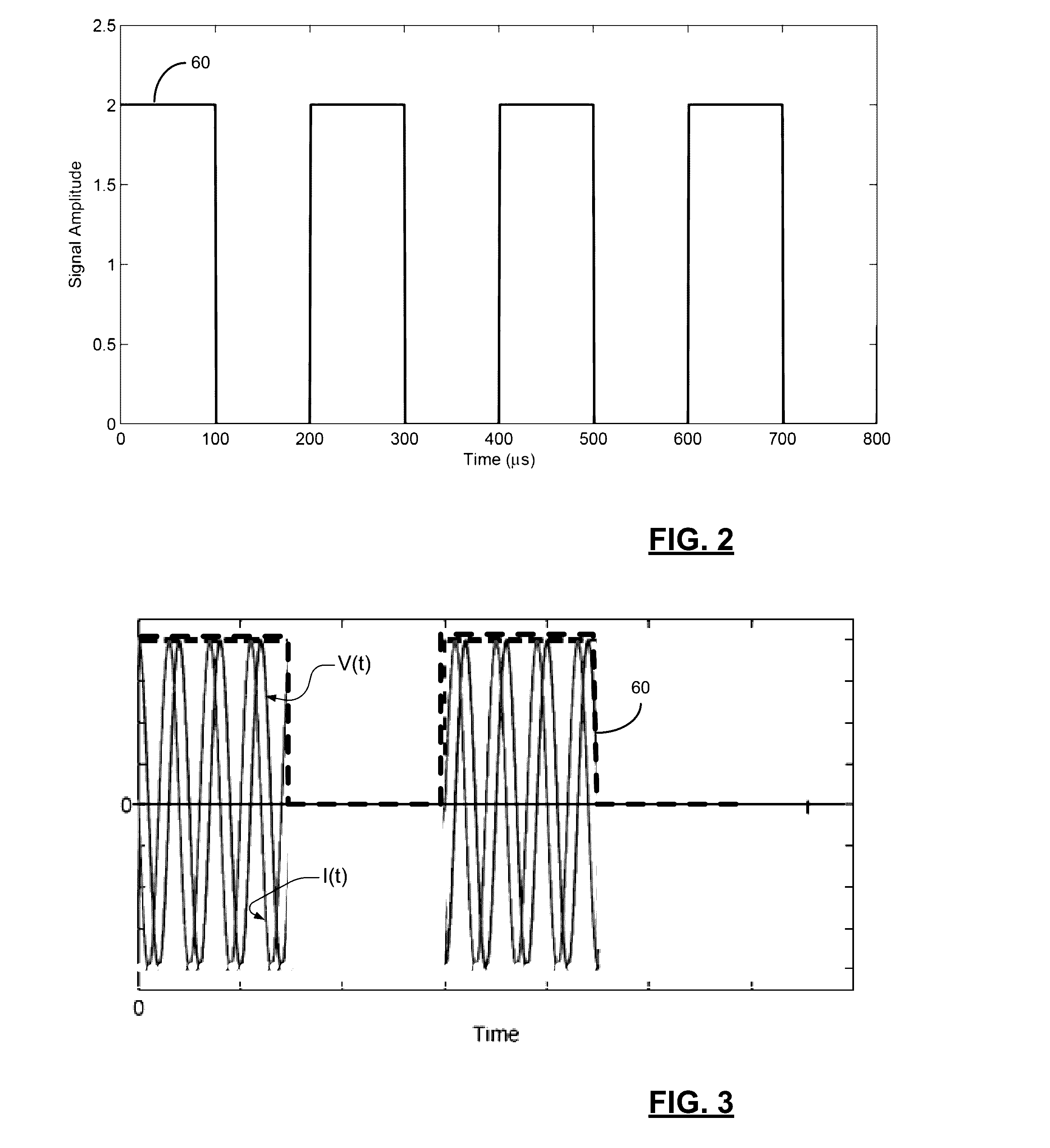
A radio frequency (RF) control system including a RF generator having a power amplifier that outputs a RF signal and a controller. A matching network receives the RF signal and generates a plurality of RF output signals. The matching network includes a ratio tuning element to vary a ratio of power between the plurality of RF output signals. The first controller communicates a ratio control signal to the matching network, and the matching network controls the ratio tuning element in accordance with the ratio control signal. The RF controls system operates in a continuous and pulse mode of operation. The controller can also control the rise or fall of a pulse edge or a level or duration of incremental changes in the pulse edge.

Description

FIELD[0001]The present disclosure relates to radio frequency (RF) power delivery systems and to centralized control of RF impedance matching networks.BACKGROUND[0002]The background description provided here is for the purpose of generally presenting the context of the disclosure. Work of the presently named inventors, to the extent it is described in this background section, as well as aspects of the description that may not otherwise qualify as prior art at the time of filing, are neither expressly nor impliedly admitted as prior art against the present disclosure.[0003]Plasma etching is frequently used in semiconductor fabrication. In plasma etching, ions are accelerated by an electric field to etch exposed surfaces on a substrate. The electric field is generated based on RF power signals generated by a radio frequency (RF) generator of a RF power system. The RF power signals generated by the RF generator must be precisely controlled to effectively execute plasma etching.[0004]A R...

Claims


Application Information

Patent Timeline
IPC IPC(8): H02J3/12
CPCH02J3/12H01J37/32082H01J37/32174H01J37/32146H01J37/32899H01J37/3299H01J37/32183H05H2242/26H05H1/46
Inventor COUMOU, DAVID J.REINHARDT, ROSSELNER, YUIRYGILL, DANIEL M.
Owner MKS INSTR INC
Learn More