

Balloon equipped with a concentrated solar generator and employing an optimised arrangement of solar cells to power said balloon in flight
- Summary
- Abstract
- Description
- Claims
- Application Information
AI Technical Summary
Benefits of technology
Problems solved by technology
Method used
Image

Examples
first embodiment
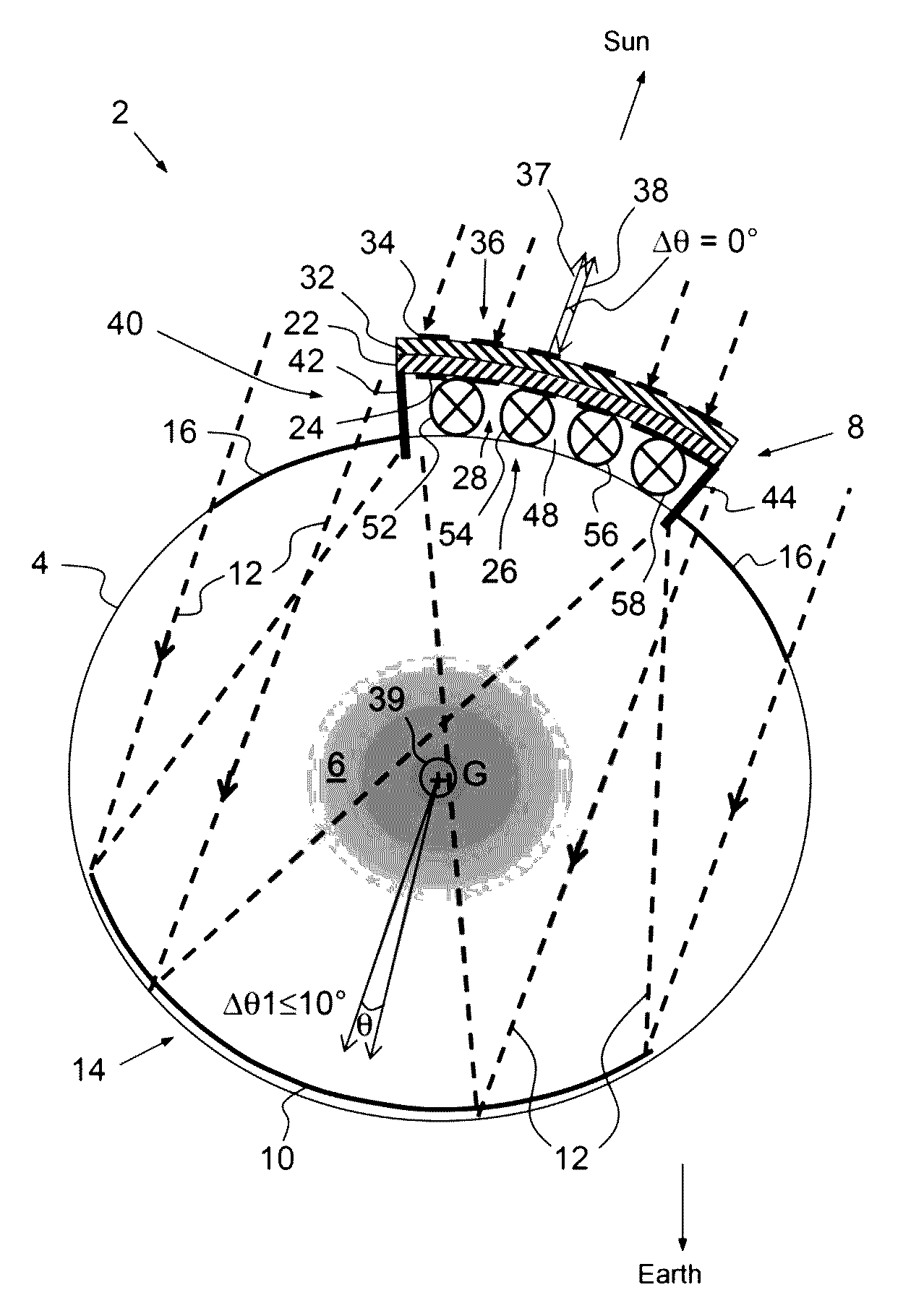
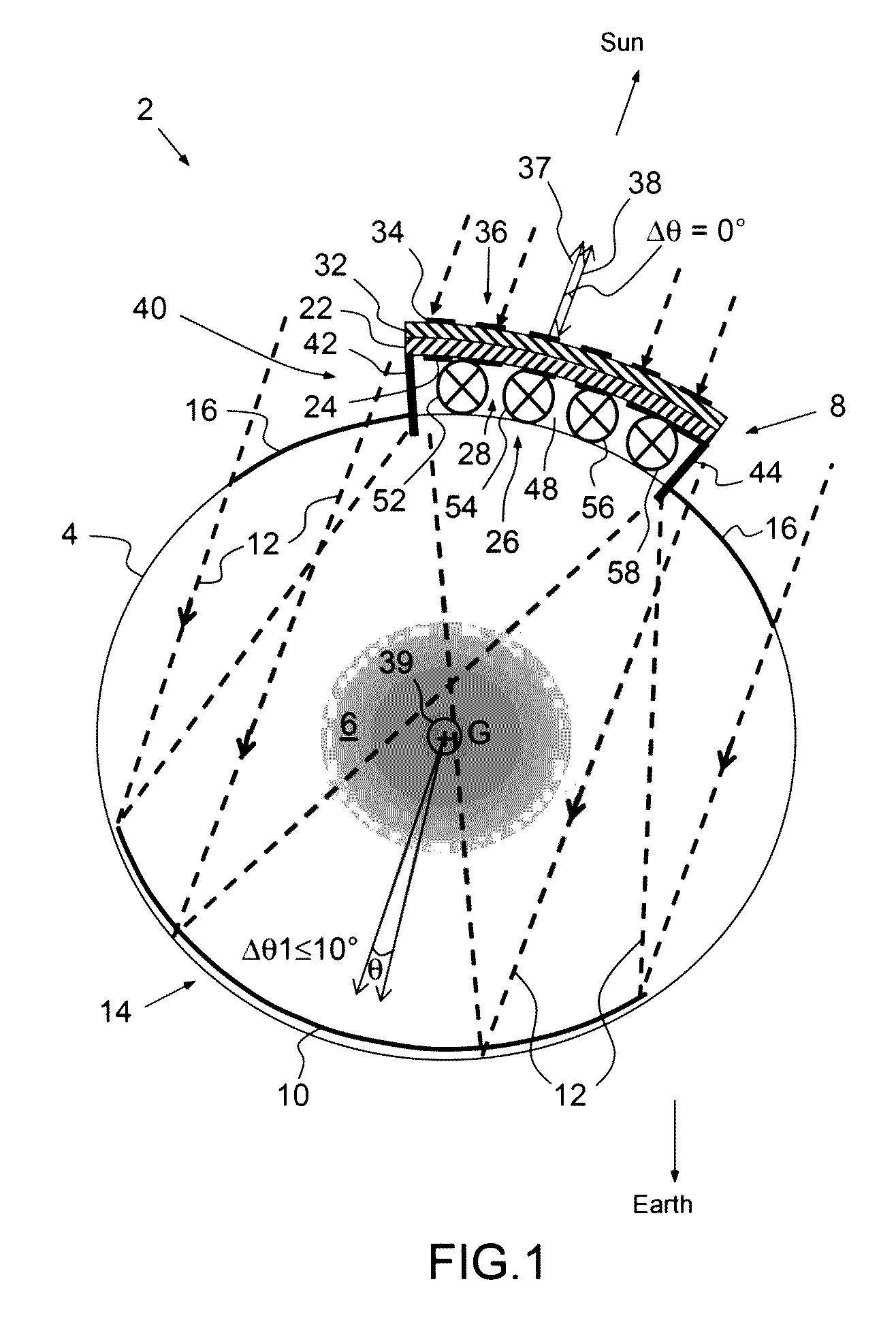
[0050]As shown in FIGS. 1 and 2 and a balloon 2, here a high-altitude balloon, comprises a positively pressurised inflated envelope 4 filled with a lifting gas 6, for example helium, and comprises a concentrated solar radiation solar generator 8.
[0051]The solar generator 8 includes a reflector 10 of solar rays 12, which reflector is placed inside the envelope 4 in a first zone 14 of the envelope, and a second zone 16 of the envelope 4, which is transparent to the solar rays, in order to let the solar rays 12 pass to the reflector 10.
[0052]The envelope 4 is for example made of reinforced polyurethane composite. The second zone 16 of the envelope 4 may be produced by using for the envelope polyurethanes that are transparent to the solar rays and by avoiding covering the second zone 16 of the envelope with a coating that would block the passage of the solar radiation.
[0053]The solar generator 8 also includes a first array 22 of single-sided photovoltaic cells 24, which array is placed...
second embodiment
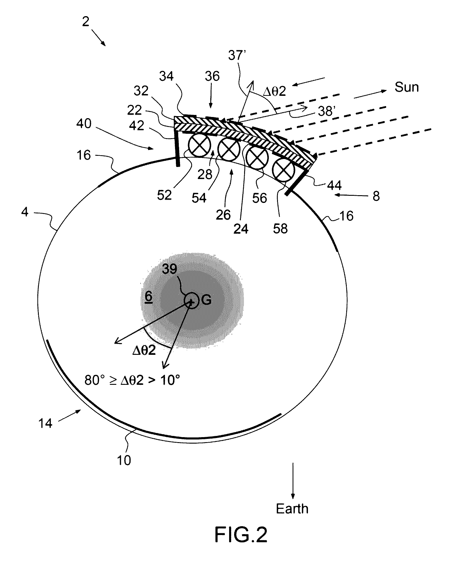
[0071]As shown in FIGS. 3 and 4 and according to the balloon according to the invention, a balloon 202 equipped with a concentrated solar generator has a similar architecture to that of the balloon 2 in FIGS. 1 and 2. As regards FIGS. 3 and 4, the attitude configurations of the balloon 202 and the illumination of the balloon by the sun are the same as those in FIGS. 1 and 2, respectively.
[0072]The balloon 202 differs from the balloon 2 in that the first and second arrays 22, 32 of photovoltaic cells form one and the same single array 204 of two-sided photovoltaic cells 206, which array is located above the third zone 26 of the envelope.
[0073]The array 204 of two-sided solar cells 206 has a first active face 208, which is oriented towards the concentrator reflector 10, and a second active face 210, which is oriented towards the exterior of the envelope 4 and has an alignment direction opposite to that of the first face 208.
[0074]Generally, the concentrating reflector 10, the second z...
PUM
 Abstract
Description
Claims
Application Information