Ac LED light engine

a led light and engine technology, applied in the direction of lighting apparatus, electrical equipment, light sources, etc., can solve the problem of the current limiter for the previous substring to shut off completely, and achieve the effect of minimal control circuitry and simplisti

Inactive Publication Date: 2017-01-19
EPTRONICS
View PDF3 Cites 30 Cited by
  • Summary
  • Abstract
  • Description
  • Claims
  • Application Information

AI Technical Summary

Benefits of technology

[0008]A light engine is described which uses a bridge rectifier to convert the AC power line voltage into a series of unidirectional half sine wave voltage pulses. Connected to the positive output terminal of the bridge rectifier is a string of LEDs, all connected anode to cathode, which are subdivided into multiple substrings and each substring has an analog current limiter connected between its cathode and the end of a string of current sense resistors. The string of current sense resistors is itself subdivided into substrings, all connected end to end, with the final resistor connected back to the negative terminal of the bridge rectifier. Each sense resistor substring controls the current through a corresponding analog current limiter. The placing of these sense resistors in series is an important feature of the invention because when each subsequent LED substring commences conducting, its current also goes through the sense resistor corresponding to the previous substring. This excessive current thus forces the current limiter for the previous substring to shut off completely. In this way each current limiter in turn is enabled and then automatically shut off as its successor is activated. Finally at the peak of the AC line voltage waveform only the current limiter for the last LED segment is operating and is regulating the current through the whole string. As the line voltage waveform declines from the peak, the situation reverses with each current limiter first operating at constant current and then switching to full on until at the line voltage zero crossing all the current limiters are fully on ready for the next half cycle. This arrangement is advantageous because the current through the LEDs is constant, avoiding extreme currents associated with voltage surges. Also the control circuitry is minimal and simplistic comprising only one quad op amp chip.

Problems solved by technology

This excessive current thus forces the current limiter for the previous substring to shut off completely.

Method used


Image

  • Ac LED light engine
  • Ac LED light engine
  • Ac LED light engine

Examples


Embodiment Construction

a) Basic Embodiment

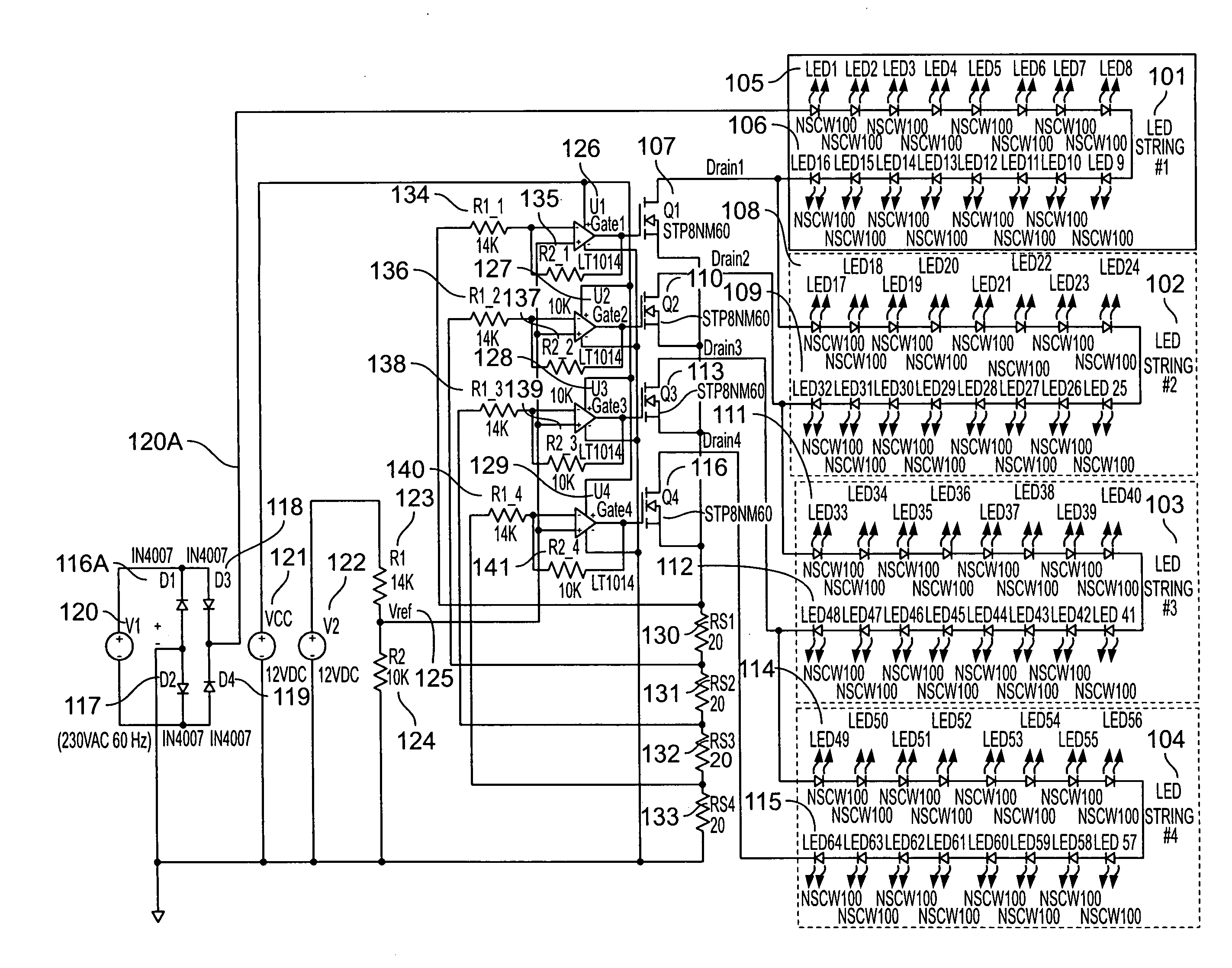
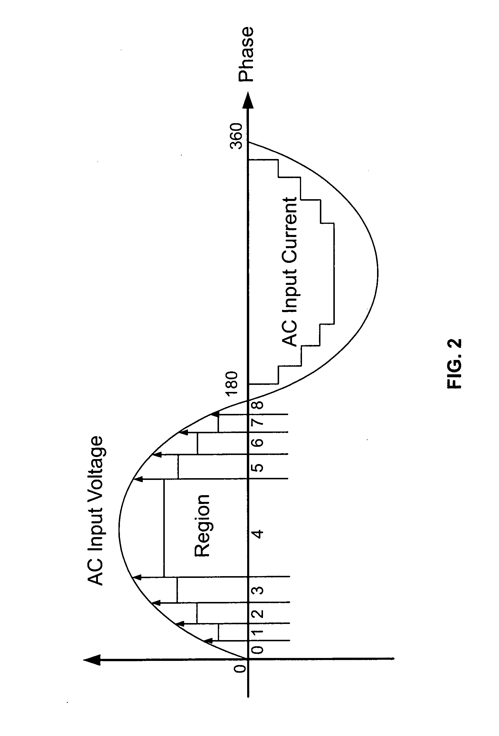
[0056]FIG. 3 shows the arrangement of a constant current ac driven light engine with four strings of LEDs. This AC LED Driver operates the LEDs in constant current mode. In each step of operation through the AC power line cycle the LEDs are operated at a relatively constant current, although that current is increased and decreased through the power line cycle in order to follow the sine wave input voltage waveform as is required to produce good power factor. The power grid input in this case is 230 VAC @60 Hz. However, the same principle applies to other voltages from 90 VAC to 382 VAC, and 47 Hz to 63 Hz applications.

[0057]The 4 steps of operation during a power line voltage half wave of operation involve sequentially turning on the 4 strings of LED's, namely LED string #1 (101), LED string #2 (102), LED string #3 (103) and LED string #4 (104). In this embodiment, each LED string has 16 LED's in series with the cathode of each connected to the anode of the next. ...


PUM


Abstract

A light engine driven directly from the AC power line has multiple series connected arrays of LEDs each with an associated current limiting transistor. The current from each current limiting transistor goes through a corresponding current sensing resistor and all these resistors are connected in series. The voltage across each current limiting transistor is applied across the next LED array so that as the voltage increases during the power line cycle, the next array becomes activated by the increasing voltage across the previous current limiting transistor. When this happens the previous current limiting transistor is turned off. This continues until all the arrays are activated at the peak of the line, at which point the array current is controlled by the last current limiting transistor.

Description

[0001]The present invention claims priority from and is a non-provisional of U.S. provisional application No. 62 / 194,033 entitled AC Led Driver In Constant Current Mode by inventors Thomas O'Neil and Lee Chiang, filed Jul. 17, 2015 the disclosure of which is incorporated herein by reference.FIELD OF THE INVENTION[0002]The field of the present invention is direct AC powered LED light engines in which the LEDs are all in series and are driven with a nearly constant current.BACKGROUND TO THE INVENTION[0003]It has become conventional in LED light engines which are to be driven directly from the rectified AC power line to arrange all the LEDs in series so that their forward voltage is just a little less than the peak of the AC line voltage. The current which passes may be limited by resistors or analog circuit current limiters. Such a circuit will only pass current at the peak of the AC power line, leading to the product having a poor power factor and high current harmonic distortion. Th...

Claims


Application Information

Patent Timeline
Patent Type & Authority Applications(United States)
IPC IPC(8): H05B33/08H05B44/00
CPCH05B33/0842H05B33/0809H05B33/083H05B45/48H05B45/345
Inventor O'NEIL, TOMCHIANG, LEE
Owner EPTRONICS
Why Eureka
Try Eureka