
Upper-limit of state-of-charge estimating device and upper-limit of state-of-charge estimating method

Active Publication Date: 2012-04-19
TOYOTA JIDOSHA KK
View PDF3 Cites 14 Cited by
  • Summary
  • Abstract
  • Description
  • Claims
  • Application Information

AI Technical Summary

Benefits of technology

[0010]According to the first aspect of the invention as described above, the use of the charging device outside the vehicle makes it possible to charge the storage device with a constant charging current. Therefore, the integrated value of charging current can be calculated with high accuracy. Also, since the storage device is charged using the external charging device while the vehicle is at rest or stopped, large variations are less likely or unlikely to appear in the state of charge of the secondary battery. Therefore, the first state of charge of the storage device at the time of start of charging and the second state of charge of the storage device at the completion of charging can be calculated with high accuracy. Accordingly, the upper limit of the state of charge of the storage device can be estimated with high accuracy, based on the first state of charge, second state of charge, and the integrated value of charging current. Thus, the invention provides the state-of-charge estimating device and state-of-charge estimating method for estimating the upper limit of the state of charge of the storage device with high accuracy.
[0016]By setting the first weight so that the first weight assigned to the first upper limit is larger than the second weight assigned to the first upper limit, the third upper limit is more likely to be reduced when the first upper limit is reduced to be smaller than the second upper limit, and the third upper limit is less likely to be increased when the first upper limit is increased to be larger than the second upper limit. Thus, the tendency of increase or reduction of the third upper limit is changed, so that the third upper limit can be changed in agreement with chronological changes of the storage device. Therefore, the upper limit of the state of charge of the storage device can be detected with high accuracy.

Problems solved by technology

However, since the state of charge of the secondary battery varies largely due to charging or discharging during running of the vehicle, the reduction of the full-charge capacity of the secondary battery may not be detected with high accuracy.

Method used


Image

  • Upper-limit of state-of-charge estimating device and upper-limit of state-of-charge estimating method
  • Upper-limit of state-of-charge estimating device and upper-limit of state-of-charge estimating method
  • Upper-limit of state-of-charge estimating device and upper-limit of state-of-charge estimating method

Examples


Embodiment Construction

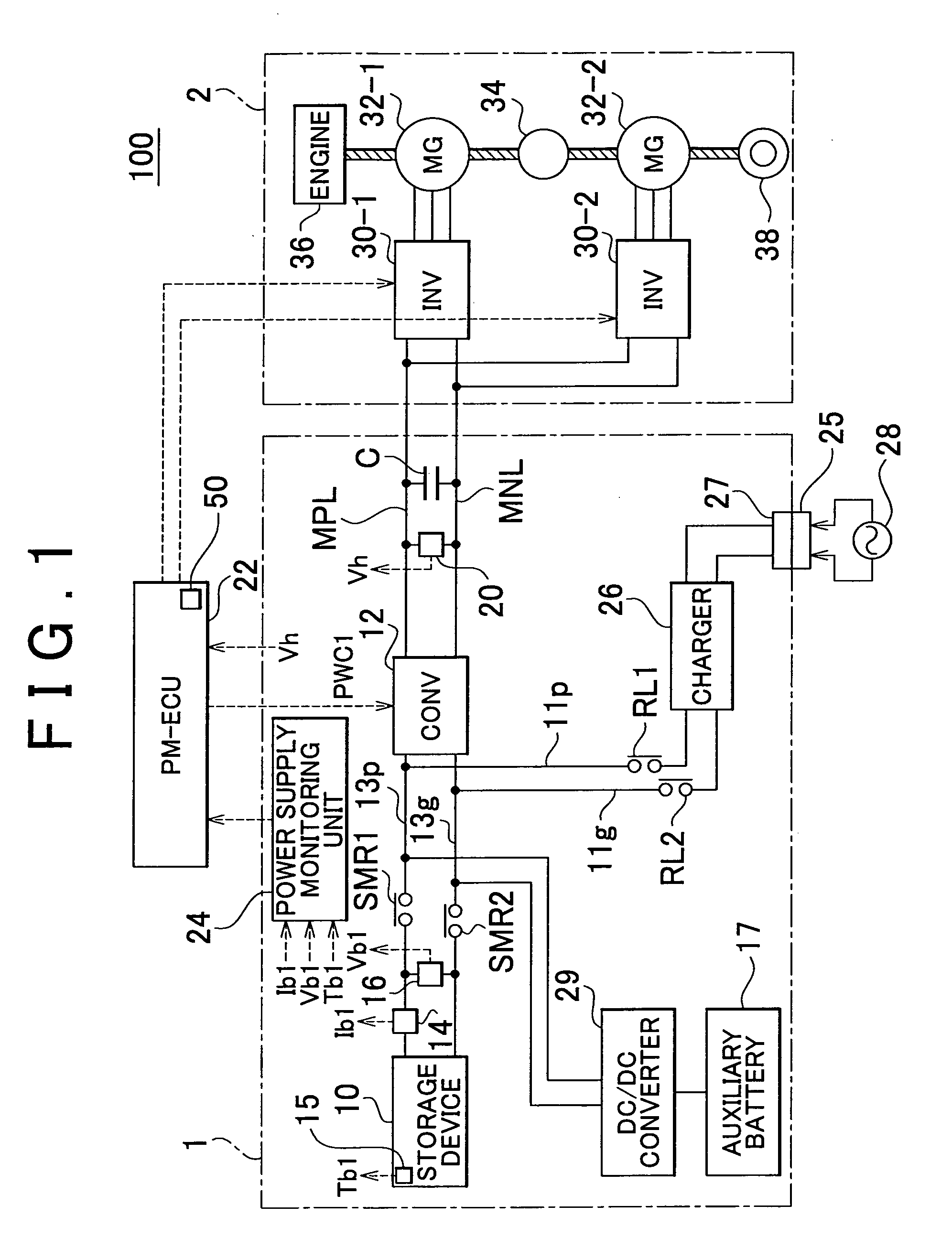
[0026]One embodiment of the invention will be described with reference to the drawings. In the following description, the same reference numerals are assigned to the same components, which have the same names and the same functions. Thus, detailed description of these components will not be repeated.

[0027]FIG. 1 is an overall block diagram of a vehicle 100 on which a state-of-charge estimating device according to the embodiment of the invention is installed. While the vehicle 100 is in the form of a hybrid vehicle in this embodiment, the vehicle 100 may be an electric vehicle that includes a motor-generator as a power source, but dos not include any engine.

[0028]As shown in FIG. 1, the vehicle 100 includes a power supply system 1, a driving force generating unit 2, and a PM(Powertrain Manger)-ECU(Electronic Control Unit) 22. The driving force generating unit 2 includes a first inverter 30-1, second inverter 30-2, first MG (Motor-Generator) 32-1, second MG 32-2, power split device 34...


PUM


Abstract

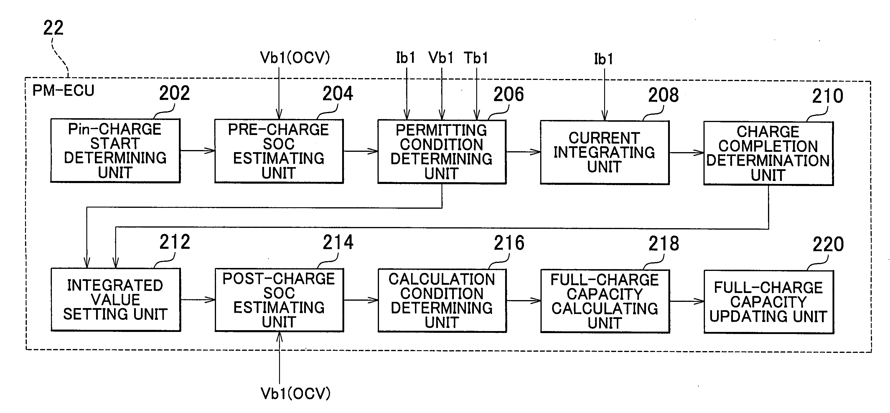
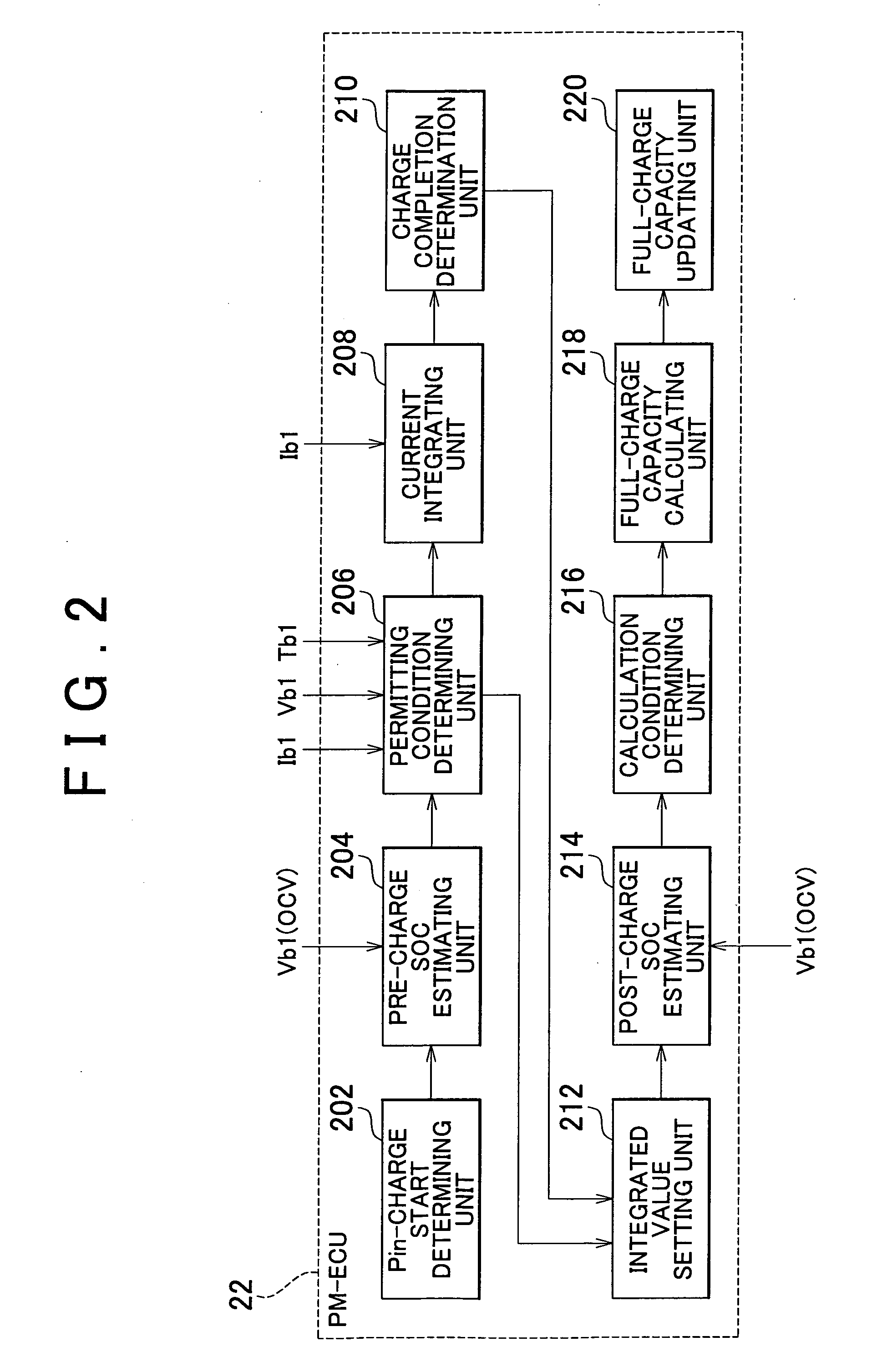
A PM-ECU executes a program including: a step (S104) of estimating pre-charge SOC(1) when a plug-in charge is started (YES in S100), a step (S108) of calculating an integrated value of charging current when integration permitting conditions are satisfied (YES in S104, YES in S106), a step (S112) of setting a final integrated value when the charge is completed, a step (S116) of estimating post-charge SOC(2) when an ignition switch is turned on (YES in S114), a step (S122) of calculating a full-charge capacity of this cycle when calculation conditions are satisfied (YES in S120), a step (S128) of calculating a new full-charge capacity when the full-charge capacity of this cycle is within a specified range (YES in S124), and a step (S130) of updating the full-charge capacity by setting the new full-charge capacity as the current full-charge capacity when the new full-charge capacity is within a specified range (YES in S128).

Description

BACKGROUND OF THE INVENTION[0001]1. Field of the Invention[0002]The invention relates to the technology of estimating the upper limit of the state of charge of a storage device that is installed on a vehicle and can be externally charged (i.e., charged with an external power supply). In particular, the invention is concerned with the technology of estimating the upper limit, based on the states of charge of the storage device before and after the external charging.[0003]2. Description of the Related Art[0004]A secondary battery that is installed on a vehicle including a dynamo-electric machine or machines as a power source and supplies electric power to the dynamo-electric machine(s) is repeatedly charged and discharged; therefore, the upper limit of the state of charge (which will also be referred to as “full-charge capacity”) of the secondary battery decreases with time due to its chronological changes. As the full-charge capacity decreases, the distance over which the vehicle can...

Claims


Application Information

Patent Timeline
IPC IPC(8): H02J7/00
CPCB60L11/1862G01R31/361Y02T10/705Y02T10/7005Y02T10/7044G01R31/3679B60L58/13G01R31/392G01R31/3828Y02T10/70
Inventor IZUMI, JUNTA
Owner TOYOTA JIDOSHA KK
Learn More