Start-up circuit for DC fan

a technology of dc fan and start-up circuit, which is applied in the direction of motor/generator/converter stopper, electronic commutator, dynamo-electric converter control, etc., can solve the problems of voltage ripples still occurring, start-up current damage or even ruin of transistors, and large amount of heat produced, so as to reduce noise, prevent a large current, and reduce current passing

Inactive Publication Date: 2009-10-06
HONG FU JIN PRECISION IND (SHENZHEN) CO LTD +1
View PDF14 Cites 14 Cited by
  • Summary
  • Abstract
  • Description
  • Claims
  • Application Information

AI Technical Summary

Benefits of technology

[0009]The digital-analog converter of the star-up circuit converts the digital control signal to the smooth analog control signal to get a linear drive. The linear drive makes working voltage of the DC fan to be zero ripples, which makes the DC fan to rotate evenly and has lower noise. Rotation speed of the DC fan and the PWM control signal are in direct proportion, to prevent a too-low rotation speed and cease of the DC fan. The start-up circuit further includes a buffer connected between the voltage sampling device and the comparator for preventing a large current in a power turn-on instant. The feedback device lowers the current passing through the switching device when the current is too high, therefore the keeping a constant current to even the rotation speed.

Problems solved by technology

During operation of many contemporary electronic devices such as central processing units (CPUs), large amounts of heat are produced.
The start-up current is liable to damage or even ruin the transistors Q70 and Q100.
In addition, although the high capacity electrolytic capacitor C63 is employed, voltage ripples may still occur.
When this happens, the fan may rotate unstably.
When a starting current passing through the transistors Q1 and Q2 is too large, the transistors Q1 and Q2 are liable to be damaged or even ruined.

Method used


Image

  • Start-up circuit for DC fan
  • Start-up circuit for DC fan
  • Start-up circuit for DC fan

Examples


Embodiment Construction

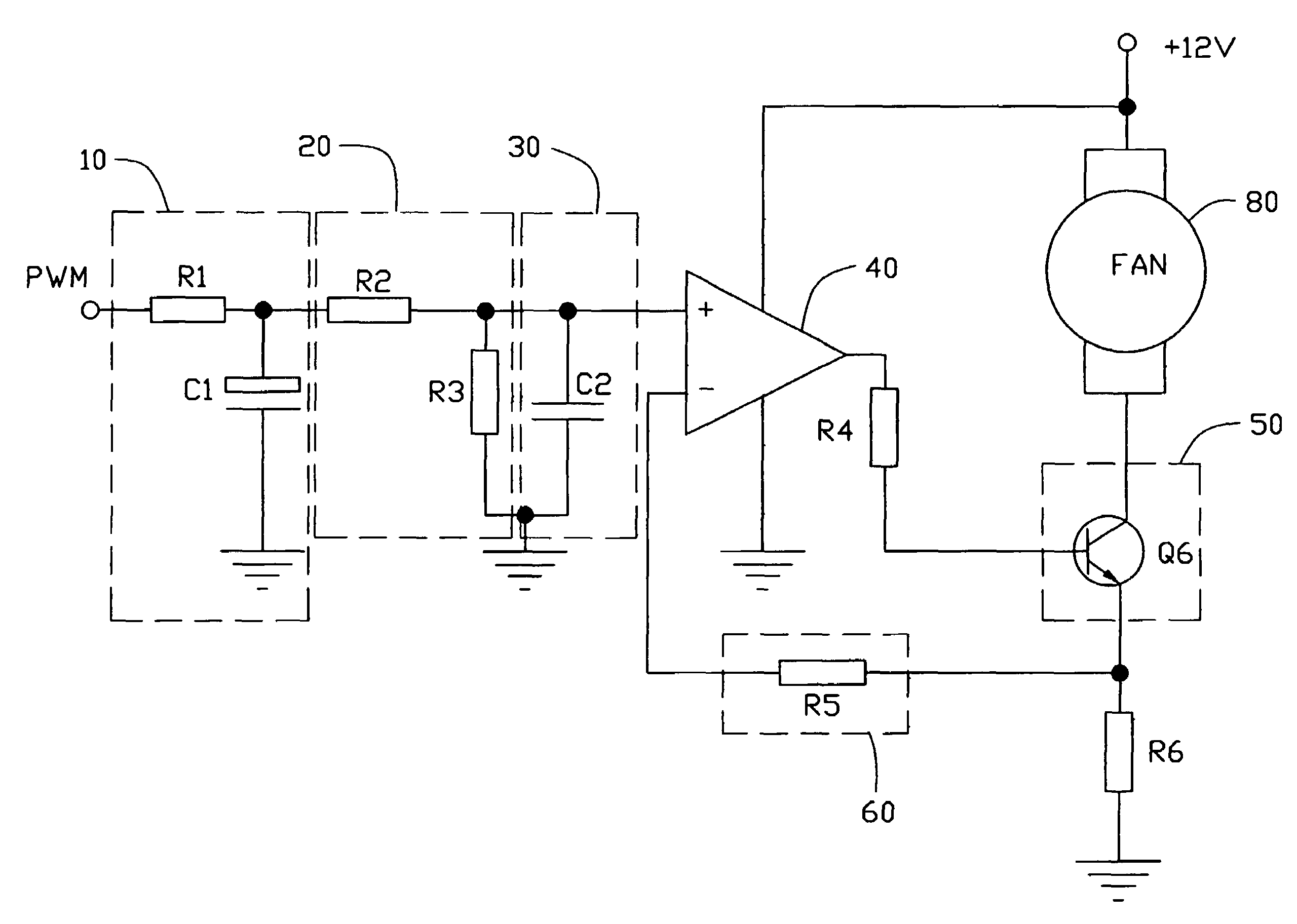
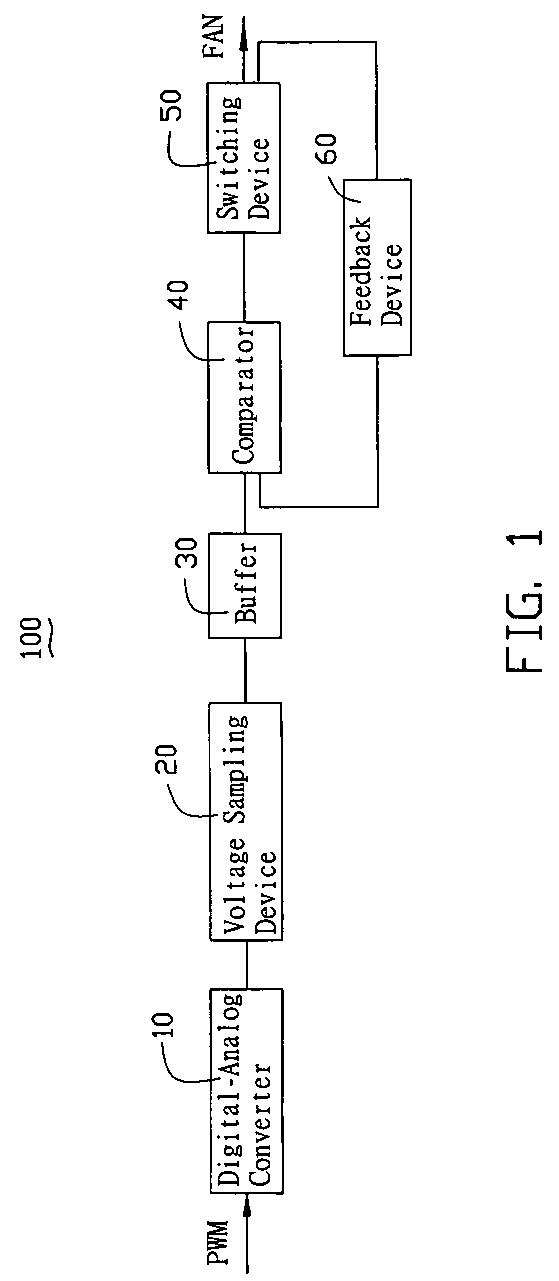
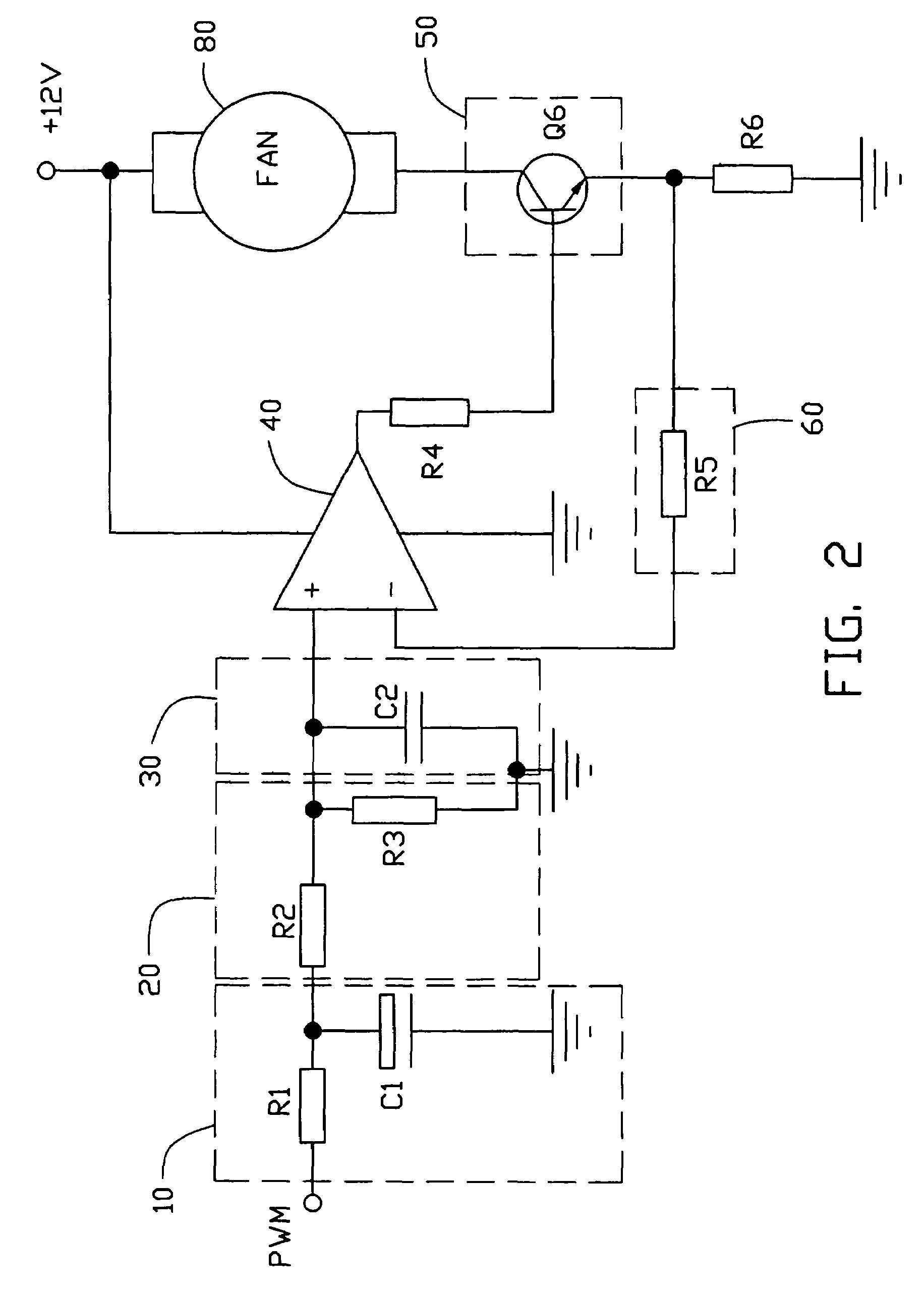
[0018]Referring to FIG. 1, a system block diagram of a start-up circuit 100 for a DC fan in accordance with first and second embodiments of the present invention is shown. A pulse width modulation (PWM) digital control signal comes from a control chip such as a Super I / O chip (not shown). The PWM digital control signal has a fixed frequency. Generally, a duty cycle of the PWM digital control signal changes according to sensed temperature. If the sensed temperature is increasing, the duty cycle increases, and a rotation speed of the DC fan increases. The start-up circuit 100 includes a digital-analog converter 10, a voltage sampling device 20, a buffer 30, a comparator 40 as a voltage stabilizer, and a switching device 50, which are connected in series. The digital-analog converter 10 converts the PWM digital control signal to a smooth analog control signal. The analog control signal is inputted to an input terminal of the comparator 40 via the voltage sampling device 20 and the buff...


PUM


Abstract

A start-up circuit which decreases a start-up current and stabilizes running of a DC fan. The start-up circuit includes a digital-analog converter for convert a digital control signal from a control chip to an analog control signal, a voltage sampling device connected to an output terminal of the digital-analog converter, a comparator, a switching device for controlling start-up of the DC fan, and a feedback device adjusting current passing through the switching device. The comparator includes two input terminals and an output terminal. One input terminal is connected to an output terminal of the voltage sampling device. The switching device is connected to the output terminal of the comparator. An output signal of the switching device is inputted to the other input terminal of the comparator via the feedback device.

Description

BACKGROUND OF THE INVENTION[0001]1. Field of the Invention[0002]The present invention relates to a start-up circuit for a direct current (DC) fan, and more particularly to a start-up circuit which has a decreased start-up current and which stabilizes running of a DC fan.[0003]2. General Background[0004]Developments in today's highly information-intensive society have led to remarkable improvements in performances of electronic devices. During operation of many contemporary electronic devices such as central processing units (CPUs), large amounts of heat are produced. Typically, an electric fan is used to facilitate removal of the heat. The fan must run stably, so as to prevent the device from becoming unstable or being damaged. A start-up circuit accompanying the fan is quite important to ensure normal running of the fan.[0005]FIG. 5 shows a conventional start-up circuit of a DC fan. A Pulse-Width Modulation (PWM) signal from a control chip directly drives transistors Q70 and Q100. ...

Claims


Application Information

Patent Timeline
Patent Type & Authority Patents(United States)
IPC IPC(8): H02P25/08
CPCH02P7/288H02P1/18
Inventor YANG, XING-JUNHE, FENG-LONGYOU, YONG-XING
Owner HONG FU JIN PRECISION IND (SHENZHEN) CO LTD
Why Eureka
Try Eureka