Dc-dc converter and converter device

a converter and converter technology, applied in the field of dc-dc converters, can solve the problems of adversely affecting the operation of other converters, affecting the output voltage, and difficulty in uniformizing the load current of each ripple converter in parallel operation

Active Publication Date: 2007-01-18
MURATA MFG CO LTD
View PDF1 Cites 18 Cited by
  • Summary
  • Abstract
  • Description
  • Claims
  • Application Information

AI Technical Summary

Benefits of technology

[0021] In order to overcome the problems described above, preferred embodiments of the present invention provide a ripple converter type DC-DC converter in which a fixe...

Problems solved by technology

In the related ripple converter, there has been a problem in that, when the duty factor changes, the output voltage varies.
Accordingly, there is a possibility that a ripple converter having a high output voltage may adversely affect the operation of other converte...

Method used


Image

  • Dc-dc converter and converter device
  • Dc-dc converter and converter device
  • Dc-dc converter and converter device

Examples


Embodiment Construction

[0051] A ripple converter type DC-DC converter according to a first preferred embodiment of the present invention is described with reference to FIGS. 1 to 5.

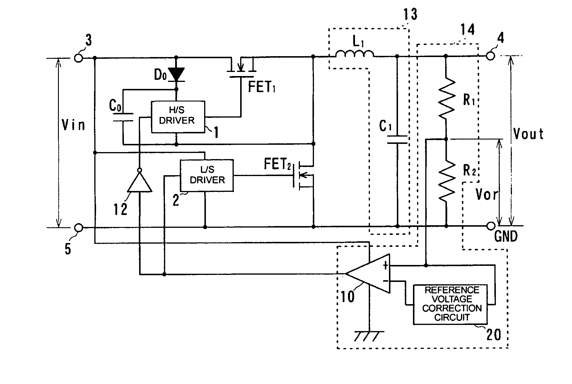
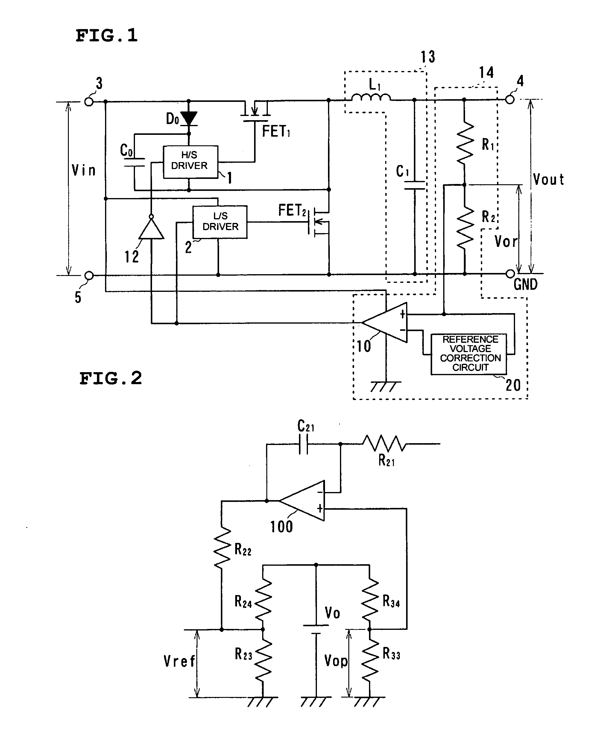
[0052]FIG. 1 is a circuit diagram showing the construction of a ripple converter of the present preferred embodiment.

[0053] Furthermore, FIG. 2 shows in detail a reference voltage correction circuit 20 in the ripple converter shown in FIG. 1.

[0054] As shown in FIG. 1, in the ripple converter of the present preferred embodiment, an N-type FET1 (hereinafter simply referred to as an FET1) and an inductor L1 are connected in order from the side of an input terminal 3 between the input terminal 3 and an output terminal 4. The drain of the FET1 is connected to the input terminal 3 and the source of the FET1 is connected to the inductor L1. Furthermore, the gate of the FET1 is connected to the control signal output terminal of an H / S driver circuit 1. Moreover, a bootstrap circuit in which a bootstrap diode D0 and a bootstrap capac...


PUM


Abstract

In a converter device, an N-type FET is connected in series between an input terminal and an output terminal and an N-type FET is connected between the side of the output terminal of the N-type FET, and a ground terminal. A smoothing circuit and a comparator circuit are connected to the side of the output terminal of the circuits. The output side of the comparator circuit is connected to an H/S driver circuit controlling the N-type FET1 through an inverter and directly connected to an L/S driver circuit controlling the N-type FET2. A reference voltage correction circuit is included in the comparator circuit, and the comparator circuit outputs an appropriate switching control signal by comparing a correction reference voltage, obtained through comparison of a divider voltage in accordance with the time average value of an output voltage with a reference voltage, with the divider voltage.

Description

BACKGROUND OF THE INVENTION [0001] 1. Field of the Invention [0002] The present invention relates to a DC-DC converter for down converting an input DC voltage to a fixed value DC voltage, that is, a ripple detection self-oscillating step-down converter and a converter device having a plurality of connected stand-alone converters. [0003] 2. Description of the Related Art [0004] Presently, low voltage and large current DC-DC converters are required due to the demand for power supply circuits in computers, etc. PWM controlled converters and ripple detection type self-oscillators (hereinafter simply referred to as ripple converters) representing such DC-DC converters are used. Since the response to load change is excellent, ripple converters, used since before the later developed PWM controlled converters, are being paid attention to once again. [0005]FIG. 12 is a circuit diagram showing the basic circuit of a ripple converter. [0006] As shown in FIG. 12, the ripple converter contains a...

Claims


Application Information

Patent Timeline
IPC IPC(8): G05F1/00
CPCH02M3/1588Y02B70/1466H02M3/285Y02B70/10
Inventor NOMA, TAKASHI
Owner MURATA MFG CO LTD
Why Eureka
Try Eureka