Method for manufacturing a metallic component by pre-manufactured bodies

Active Publication Date: 2017-01-26
MTC POWDER SOLUTIONS AB
View PDF3 Cites 10 Cited by
  • Summary
  • Abstract
  • Description
  • Claims
  • Application Information

AI Technical Summary

Benefits of technology

[0013]The pre-manufactured coherent body 1, 2, 3, 4 used in the method as defined hereinabove or hereinafter may be handled without the risk of breaking. This makes it possible to position the pre-manufactured coherent body with high accuracy in the HIP capsule and when several bodies of different materials, such as two or more, are arranged in the capsule, there is no risk that the different materials mix.
[0014]The entire pre-manufactured coherent body 1, 2, 3, 4 may consist of sintered metallic powder. Hence, the entire pre-manufactured coherent body 1, 2,

Problems solved by technology

A drawback with this technique is that it is quite difficult to control powder separation when the template is removed.
The technique is also quite limited with regards to size and geometry of the different powder re

Method used


Image

  • Method for manufacturing a metallic component by pre-manufactured bodies
  • Method for manufacturing a metallic component by pre-manufactured bodies
  • Method for manufacturing a metallic component by pre-manufactured bodies

Examples


Embodiment Construction

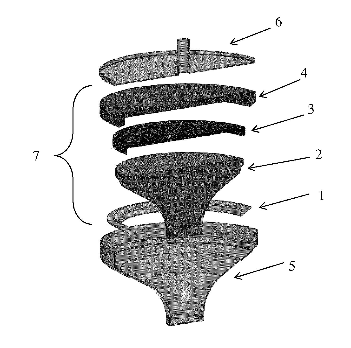
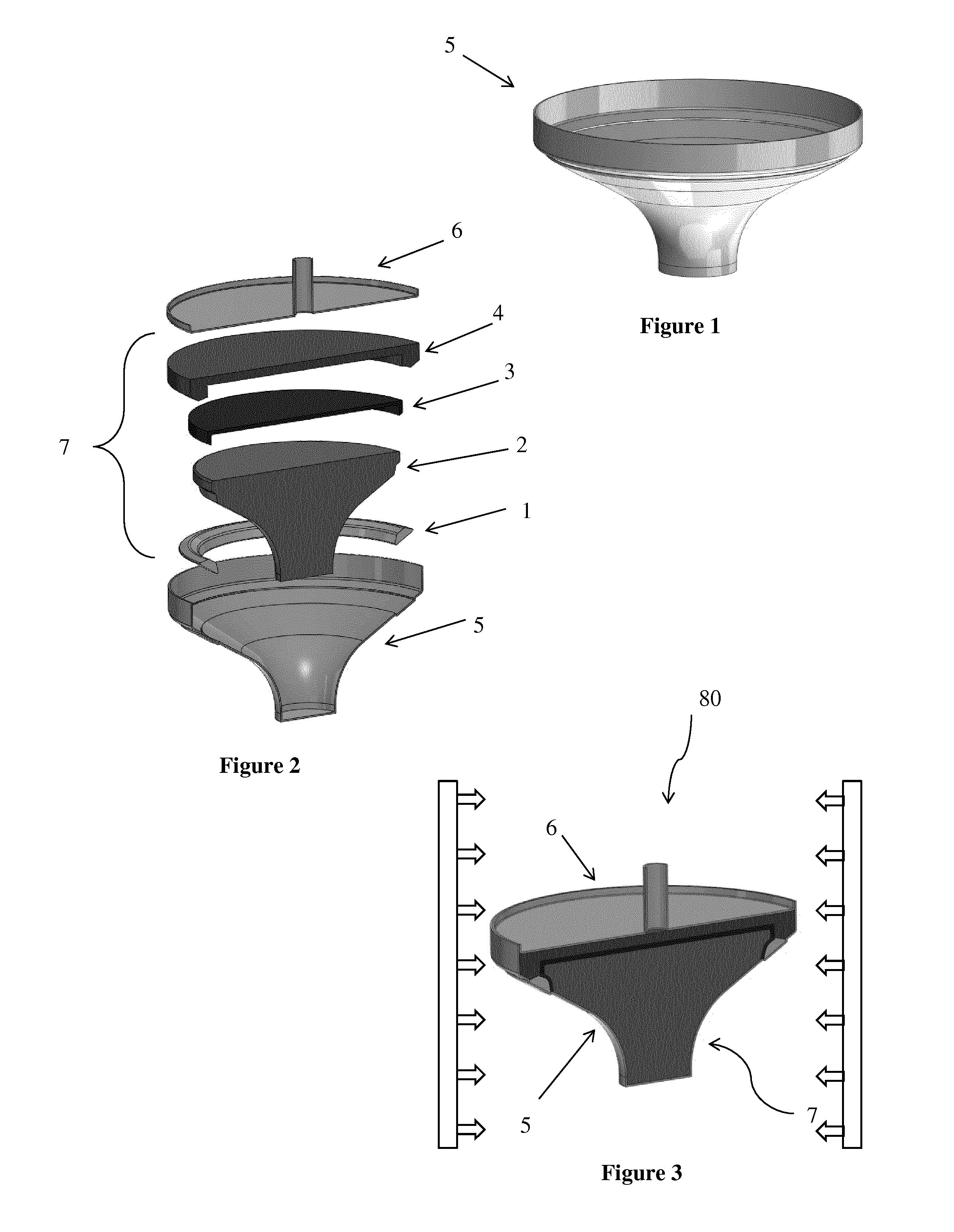
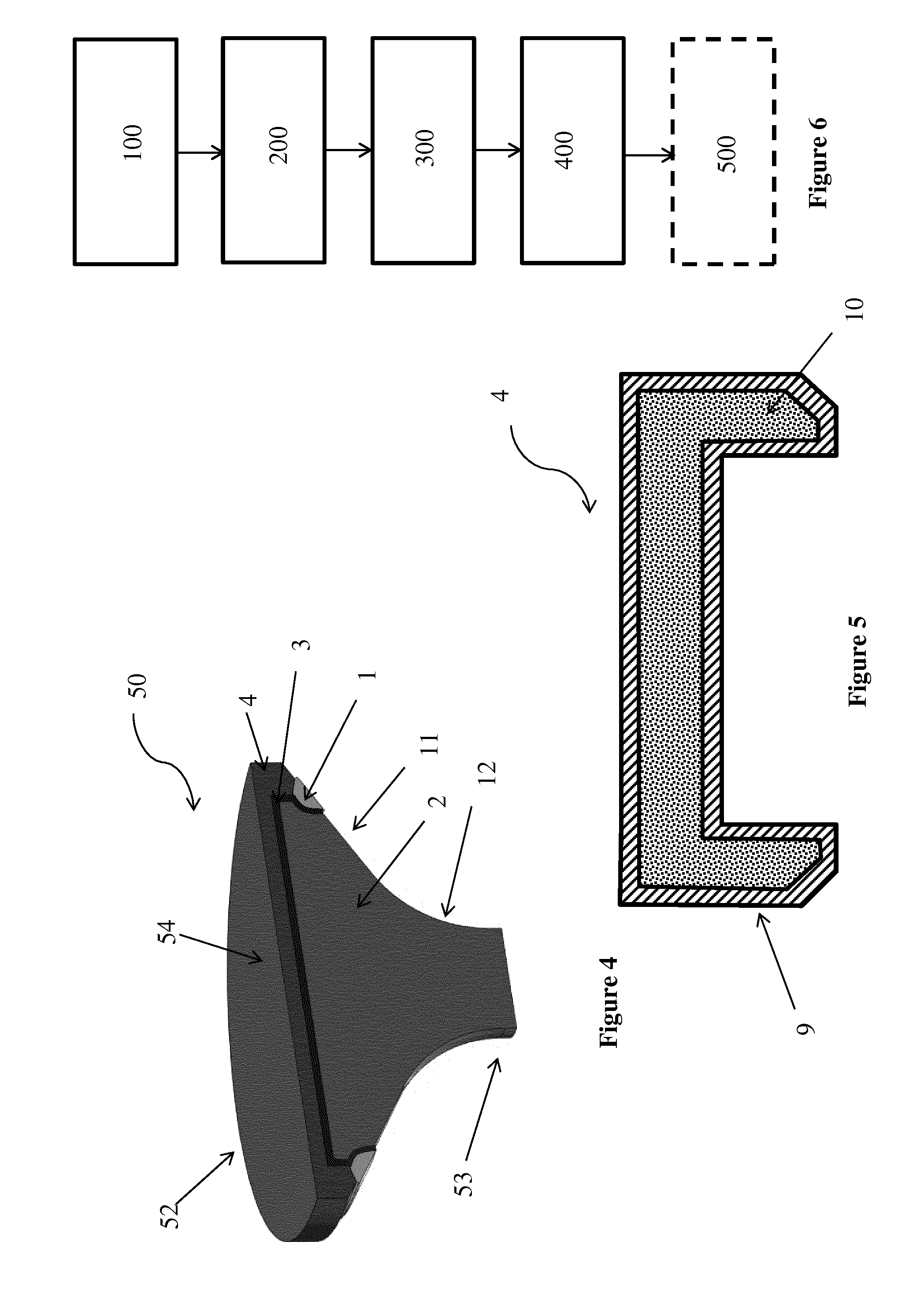
[0030]The method as defined hereinabove and hereinafter will in the following be described in detail with reference to the manufacturing of a metallic component in the form of a valve spindle. The general order of the main steps of the inventive method is shown in the flow chart of FIG. 6.

[0031]The described embodiment relates to the manufacturing of a valve spindle for two-stroke marine diesel engines. However, this is not to be understood as limiting for the present disclosure, it should be appreciated that the inventive method is suitable for the manufacturing of all types of metallic components, for example impellers, fuel nozzles, rotor shafts and stress-o-meter rings.

[0032]FIG. 4 shows schematically, in cross-section, a perspective view of a valve spindle 50 obtained by the present method. The valve spindle 50 comprises a stem 53 and valve disc 52. The valve disc has a flat upper surface 54, which in the engine faces the cylinder room. The flat surface 54 is also called the ex...


PUM

PropertyMeasurementUnit
Temperatureaaaaaaaaaa
Metallic bondaaaaaaaaaa
Melting pointaaaaaaaaaa

Abstract

A method for manufacturing a metallic component including the steps of providing a capsule, which defines at least a portion of the shape of the metallic component, arranging metallic material in the capsule, sealing the capsule, subjecting the capsule to Hot Isostatic Pressing for a predetermined time, at a predetermined pressure and at a predetermined temperature, and optionally, removing the capsule. The metallic material is at least one pre-manufactured coherent body, which pre-manufactured coherent body being made of metallic powder, wherein at least a portion of the metallic powder is consolidated such that the metallic powder is held together into a pre-manufactured coherent body. At least one portion of the pre-manufactured coherent body is manufactured by Additive Manufacturing by subsequently arranging superimposed layers of metallic powder.

Description

TECHNICAL FIELD[0001]The present disclosure relates to a method for manufacturing a metallic component according to the preamble of claim 1.BACKGROUND ART[0002]Hot Isostatic Pressing (HIP) is a preferred method for manufacturing components of near net shape and in high performance materials. In HIP, a capsule is defining the shape of the component and is typically manufactured from steel sheets. The capsule is filled with metal- or composite powder and subjected to high temperature and high isostatic pressure so that the metal powder bond metallurgically to a dense component of forge like strength.[0003]Hot Isostatic Pressing is suitable for manufacturing components having regions of different material. Typically, such components are manufactured by adding the different materials in powder form into the capsule. To achieve the desired properties of each separate material, it is thereby critical to avoid mixing of the different powders.[0004]A common technique to position the differe...

Claims


Application Information

Patent Timeline
IPC IPC(8): B22F5/00B22F3/15F16K27/00B22F3/10B33Y10/00B33Y80/00B22F3/11B22F3/16
CPCB22F5/008B22F3/11B22F3/15B22F3/16B22F2998/10B33Y10/00B33Y80/00F16K27/00B22F3/1017B22F3/1208B22F7/062F01L3/02B22F10/64B22F10/14B22F10/28B22F3/10F01L3/00F01L2303/00Y02P10/25B22F10/10
Inventor BERGLUND, TOMASSANDBERG, RICKARDOSTLUND, MARTINSUNDSTROM, JOHAN
Owner MTC POWDER SOLUTIONS AB
Why Eureka
Try Eureka