

Steering wheel
a steering wheel and cylinder technology, applied in the field of steering wheels, can solve the problems of weak vibrations transmitted to the rim, high production cost of steering wheels, and large weight of steering wheels, and achieve the effect of easy and stably attaching the electric motor to the arm and maintaining stably for a long tim
- Summary
- Abstract
- Description
- Claims
- Application Information
AI Technical Summary
Benefits of technology
Problems solved by technology
Method used
Image

Examples
first embodiment
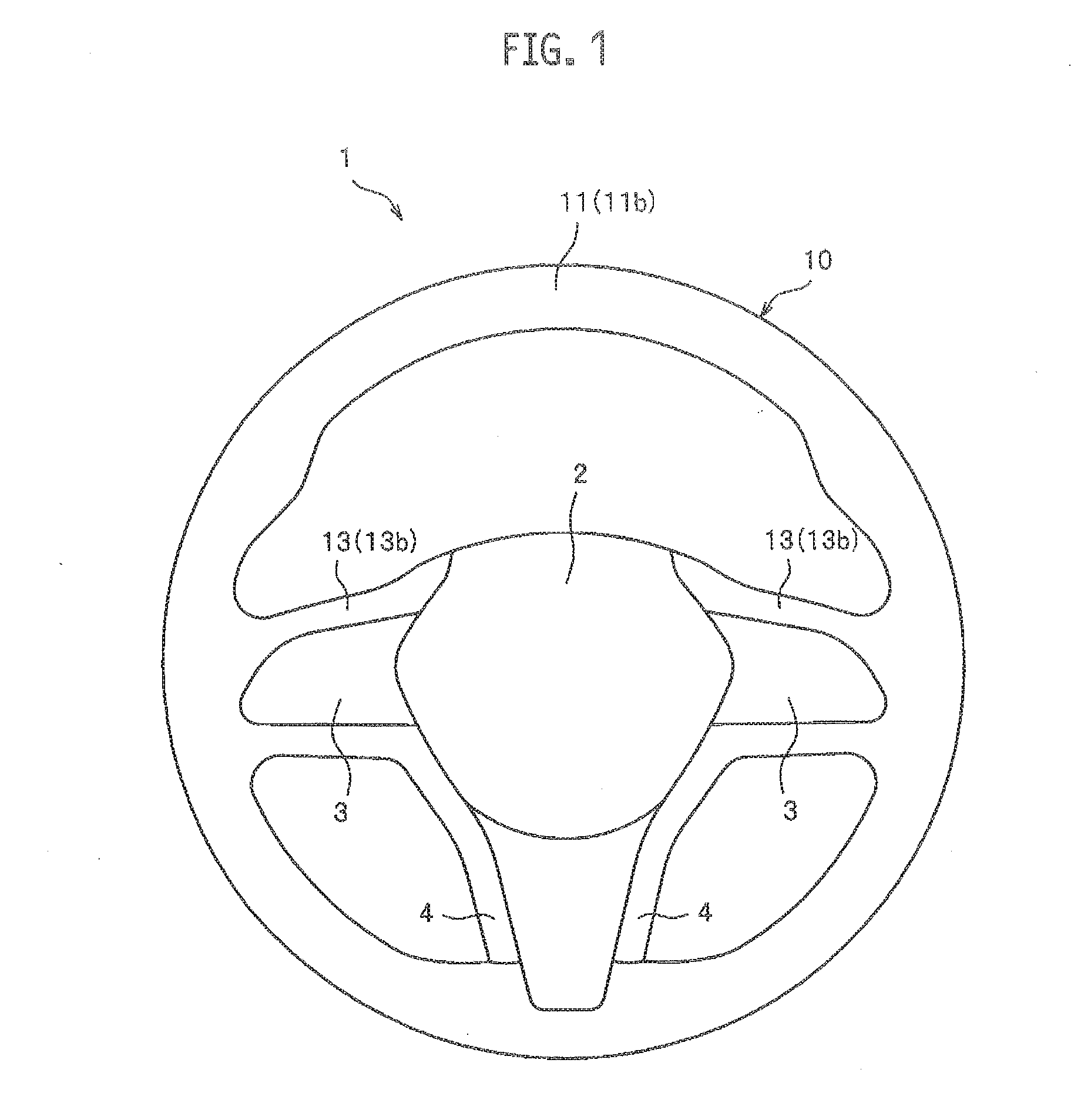
[0038]As shown in FIG. 1, a steering wheel 1 according to a first embodiment includes a main body 10, a center pad 2, finishers 3, a rear cover (not shown), and a vibration controller (not shown). The center pad 2 is disposed on a front-face side of the main body 10, and accommodates an airbag module therein. The finishers 3 are disposed on both left and right sides of the center pad 2 to cover a front face of the main body 10. The rear cover covers a rear face of the main body 10. The vibration controller controls operations of an after-described vibration generator 15 (see FIG. 2).
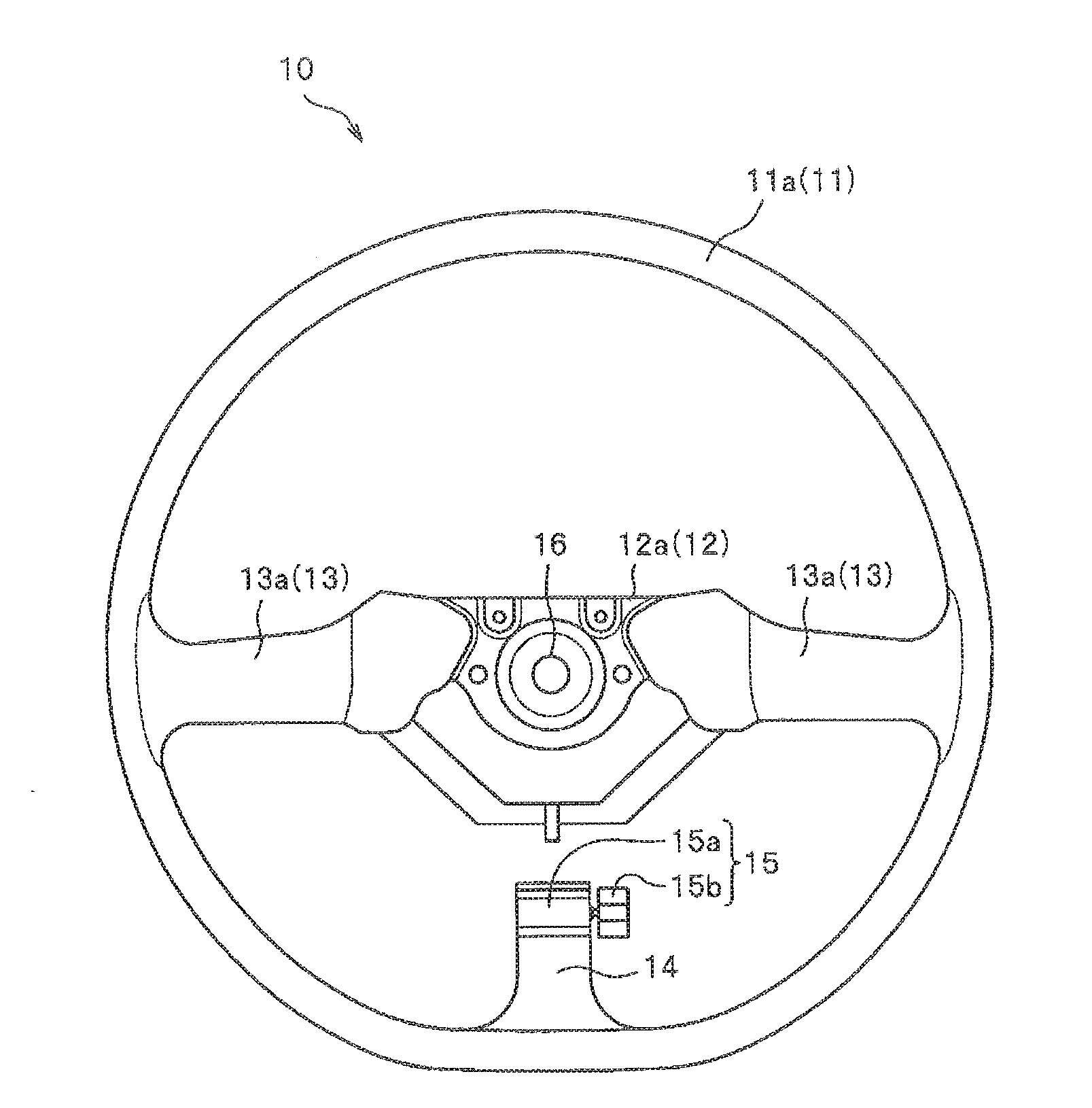
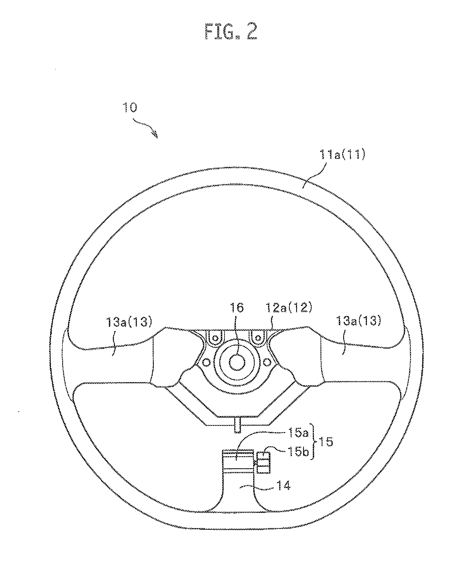
[0039]As shown in FIG. 2, the main body 10 includes a ring-shaped rim 11, a boss 12, spokes 13, an arm 14, and the vibration generator 15. The rim 11 is to be gripped by a driver. The boss 12 is disposed at the center of the rim 11. The spokes 13 connect the rim 11 with the boss 12. The arm 14 is extended upward from a lower end of the rim 11. The vibration generator 15 is attached to an open-end portion...
second embodiment
[0064]A steering wheel according to a second embodiment is different from the steering wheel 1 according to the above-described first embodiment only in configurations of an arm 24 extended from the rim core 11a and an attachment bracket 21 for attaching the vibration generator 15 to the arm 24. Other configurations of the steering wheel according to the second embodiment are substantially equivalent to those of the steering wheel 1 according to the above-described first embodiment.
[0065]Therefore, in the second embodiment (and also in after-described third and fourth embodiments), portions and members having substantially equivalent configurations to those of the steering wheel 1 according to the first embodiment will be labelled with identical reference numbers to those in the first embodiment, and their detailed descriptions will be omitted.
[0066]As shown in FIG. 6, the arm 24 in the present embodiment is extended from the lower end (6-o'clock position) of the rim core 11a toward...
third embodiment
[0081]In a steering wheel according to a third embodiment, the electric motor 15a of the vibration generator 15 is attached to an arm 34 extended from the rim core 11a, not by using an adhesive agent as in the above-described first embodiment, but by providing a structure for snapping the electric motor 15a on the arm 34. Other configurations of the steering wheel according to the third embodiment are substantially equivalent to those of the steering wheel 1 according to the above-described first embodiment.
[0082]As shown in FIG. 9 and FIG. 10, the arm 34 in the present embodiment is extended from the lower end (6-o'clock position) of the rim core 11a toward the boss core 12a, and has a constant width. The arm 34 is formed integrally with the rim core 11a by casting, metal injection molding and so on. One end of the arm 34 is connected with the rim core 11a, and the other end thereof forms a free end as a cantilever. In addition, a motor snap-on / accommodation portion 31 for fixing t...
PUM
 Abstract
Description
Claims
Application Information