Automation facility and method for expanding the automation facility with at least one field device

Active Publication Date: 2017-01-26
SIEMENS AG
View PDF0 Cites 2 Cited by
  • Summary
  • Abstract
  • Description
  • Claims
  • Application Information

AI Technical Summary

Benefits of technology

The present invention provides an automation facility and method that simplifies the expansion of the facility. The user can plan and connect virtual field devices to the automation facility, which are emulated based on real field devices. The current communication and control load are constantly shown, guiding the expansion of the automation facility towards the communication and control load limits. This results in a safe and gradual expansion of the facility, without the need for a "shadow automation facility" and avoiding shutdowns of production. The invention simplifies the process of expanding the automation facility and increases efficiency.

Problems solved by technology

If, however, the current communication or the current control load exceeds the respective load limit after a virtual field device has been connected, then an expansion of the existing automation facility with the real field device that was emulated by this connected virtual field device is not possible.

Method used


Image

  • Automation facility and method for expanding the automation facility with at least one field device
  • Automation facility and method for expanding the automation facility with at least one field device
  • Automation facility and method for expanding the automation facility with at least one field device

Examples


Embodiment Construction

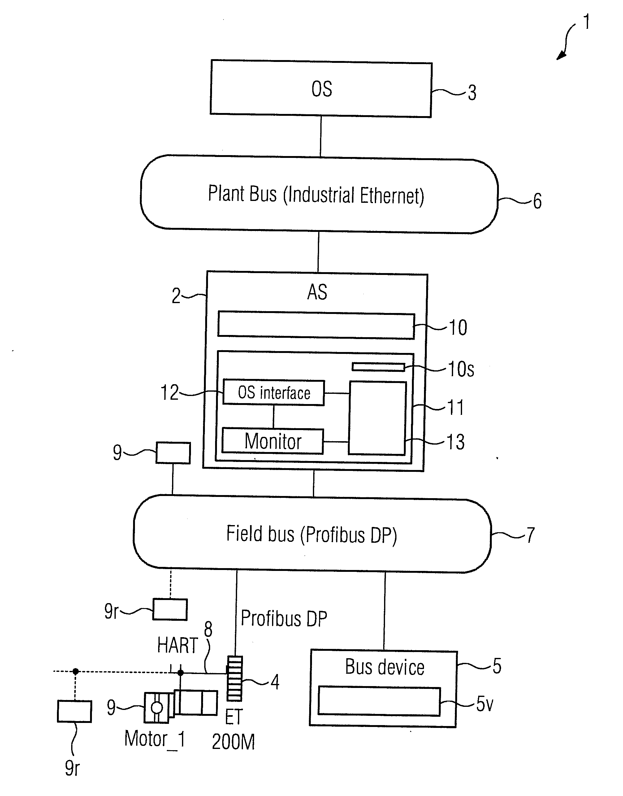
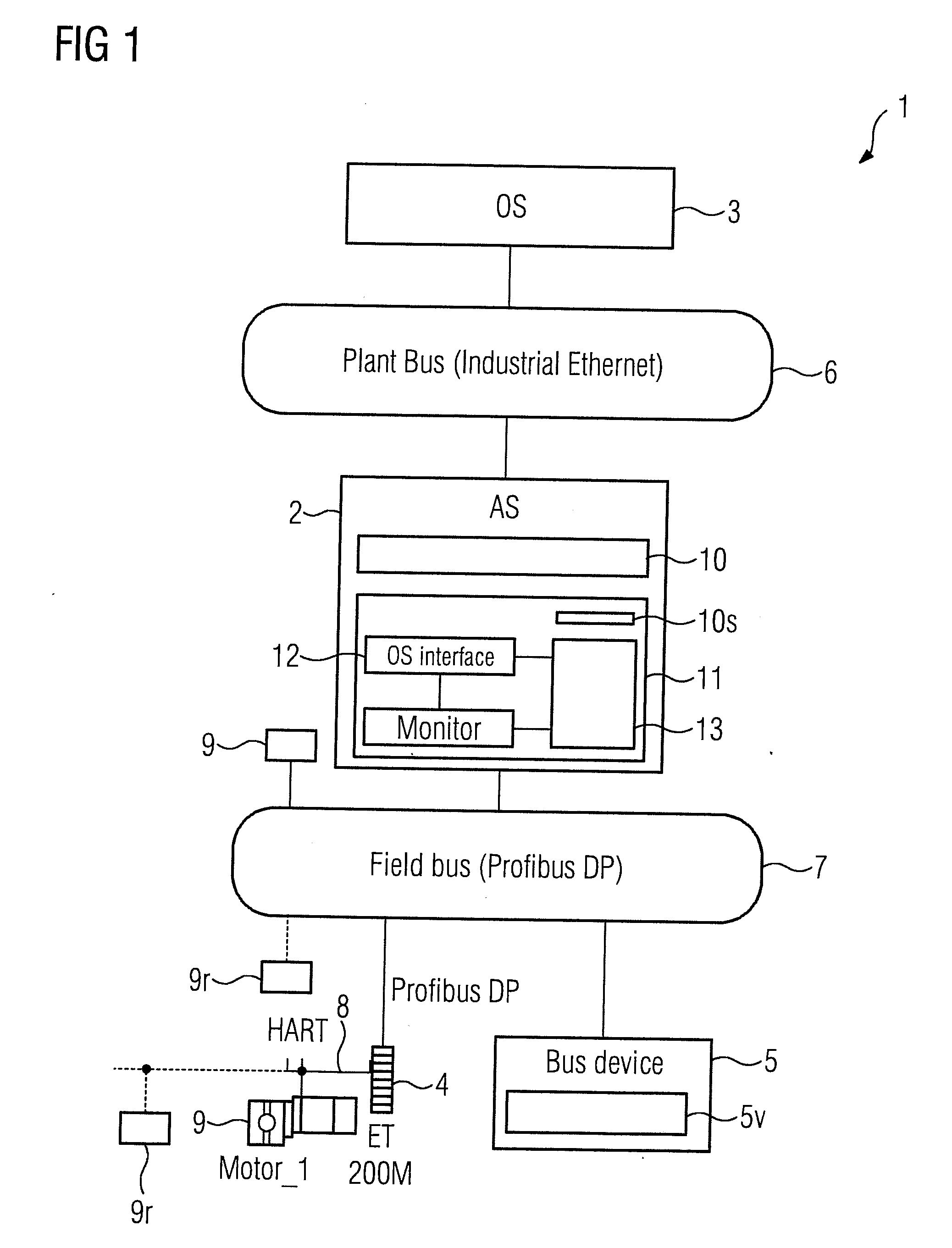
[0018]Shown in FIG. 1 by the number 1 is an automation facility 1 planned into a project by an engineering system (not shown). In the present exemplary embodiment, this comprises an automation device 2, an OS client or an operator control and monitoring device 3 of an OS operator system, which also has an OS server (not shown), a decentralized periphery 4 and a communication user 5. The automation device 2 communicates with the OS client 3 via a communication link 6 and via a further communication link 7 with the decentralized periphery 4 and the communication user 5, where the communication links 6, 7 are formed as bus connections. A plurality of field devices 9 (e.g., actuators, or sensors) is connected to the bus 7 and / or to a further bus 8 connected to the decentralized periphery 4 where, during the process control, i.e., during the run operation of the automation device 2, the field devices 9 are controlled by control modules. These control modules are components of a control p...


PUM


Abstract

An automation facility and method for expanding the automation facility with at least one field device, wherein expansion of the expansion of the automation facility with a further field device occurs in a simplified manner such that no disruptive influence on process control during the expansion occurs.

Description

BACKGROUND OF THE INVENTION[0001]1. Field of the Invention[0002]The invention relates to an automation facility and method for expanding the automation facility with a field device, where the automation facility has at least one automation device and at least one field device that are connected to a communication link, and where the automation facility is further planned into a project by an engineering method for solving an automation problem such that the at least one automation device processes a control program comprising a plurality of control modules planned into the project while controlling a process.[0003]2. Description of the Related Art[0004]Siemens Catalog “Process Control System SIMATIC PCS 7, Edition 2014 / 15, Chapter 4”, discloses an engineering system of an automation facility that is configured to plan both hardware and software automation components of the automation facility into a project, where especially as part of an “engineering of the automation”, a user crea...

Claims


Application Information

Patent Timeline
IPC IPC(8): G05B19/418
CPCG05B19/41835G05B2219/31229G05B2219/32128G05B19/048G05B19/4183G05B19/0426G05B19/056G05B2219/25428G05B2219/31018G05B2219/31135G06F30/17G06F30/20
Inventor DRUMM, OLIVERHECK, CHRISTIANKRAUS, ROLFLUTZ, BENJAMINWOLF, GERRIT
Owner SIEMENS AG
Why Eureka
Try Eureka