Protective Device with Self-Test

a protection device and self-testing technology, applied in the direction of electrical apparatus, arrangements responsive to excess voltage, arrangements resposes to fault current, etc., can solve the problems of electrical arcing, failure of all products relying on electronic components and mechanical parts, and combustible ignitan

Active Publication Date: 2017-01-26
PASS SEYMOUR
View PDF1 Cites 12 Cited by
  • Summary
  • Abstract
  • Description
  • Claims
  • Application Information

AI Technical Summary

Benefits of technology

[0053]In a version of the embodiment, at least one end-of-life condition in the arc fault detection circuit does not interfere with the ability of the control circuit to effect a test cycle or interfere with the ability of the device to interrupt a ground fault condition.
[0054]In one embodiment, the control circuit is configured to compare a test result to a predetermined successful test outcome for each test in the series of tests, each test result being an element of a test result table that includes all of the test results for all of the tests in the series of tests over a predetermined number of cycles, the control circuit being configured to effect an end-of-life state in accordance with a predetermined voting scheme that employs the elements of the test result table.

Problems solved by technology

Electrical arcing is a fire hazard because it can ignite combustible materials (such as those used to construct residential or commercial structures).
All products that rely on electronic components and mechanical parts eventually fail over time.
Unfortunately, users routinely ignored those instructions and many devices were installed but no longer functioning.
This gives the needed time to perform the test without nuisance tripping risk but unfortunately the device is unresponsive to real fault conditions that could be happening during a recurring test period.
In one drawback to this approach, the auto-testing process extended into the next half cycle and nuisance tripping was found to occur.
Another drawback to this approach relates to the need to operate a power supply during both half-cycles of the AC line cycle.
The full-wave power supplies often add cost and complexity.
While each test portion avoids nuisance tripping by taking less than a half cycle to perform, this method also has drawbacks.
For example, while this process avoids nuisance tripping, the self-test procedure does not test the way the protective device truly operates when it senses and detects an authentic fault condition.
Another drawback to this approach relates to the fact that, when taken together, the multiple test portions fail to test every part of the protective device.
One reason for this outcome is that the device is configured to operate in a sequential manner, and when the testing is not performed sequentially, there are certain parts of the device that “are hard to reach” by separate and discrete tests (in fact, these circuits are typically not tested).
Another drawback to this approach relates to the electronic components that are getting tested separately; while these parts are subject to some testing, the test does not subject them to the conditions they experience during a true fault condition.
Another problem that arises relates to miswiring the device.

Method used


Image

  • Protective Device with Self-Test
  • Protective Device with Self-Test
  • Protective Device with Self-Test

Examples


Embodiment Construction

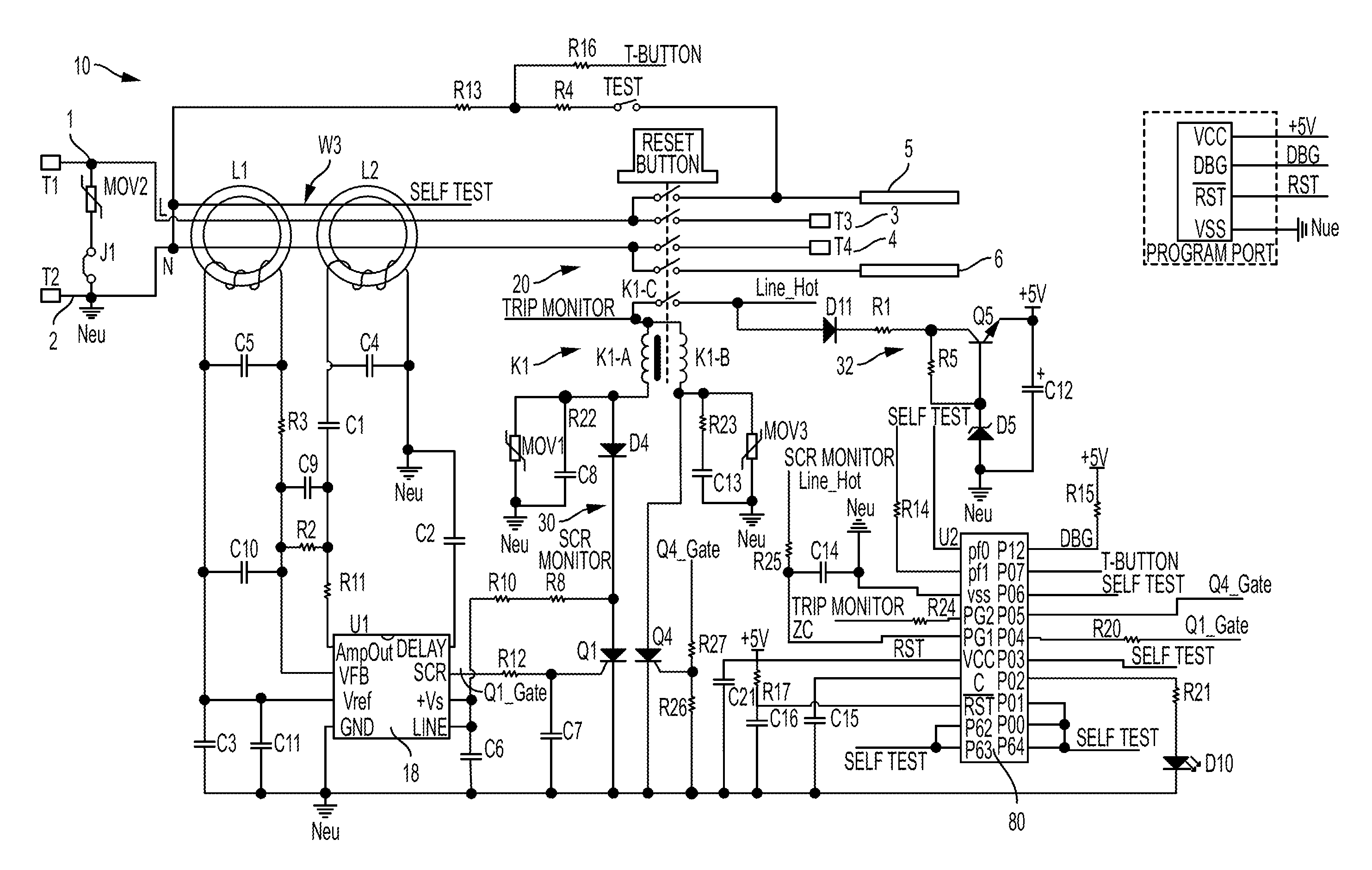
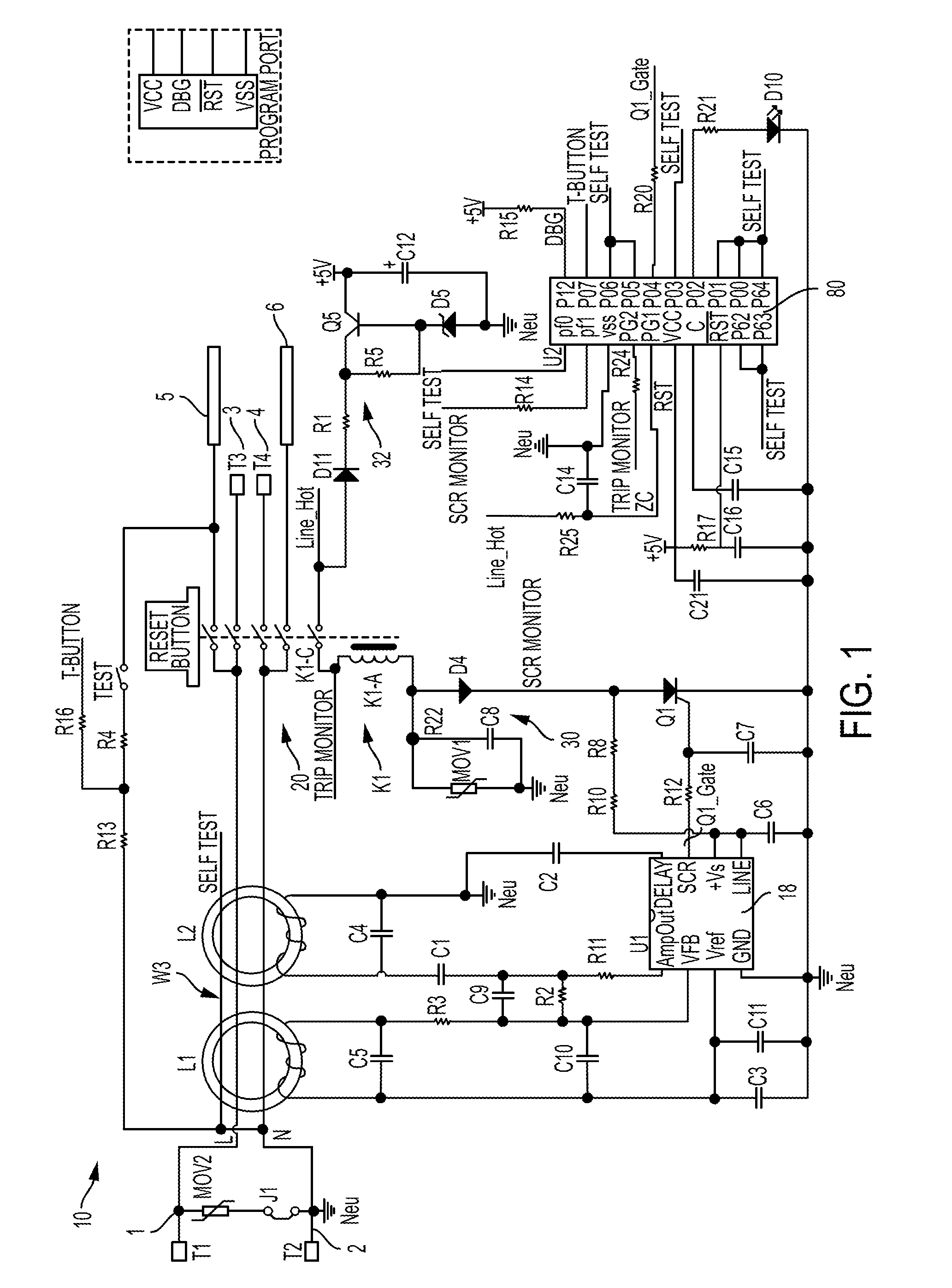
[0073]Reference will now be made in detail to the present exemplary embodiments of the invention, examples of which are illustrated in the accompanying drawings. Wherever possible, the same reference numbers will be used throughout the drawings to refer to the same or like parts. An exemplary embodiment of the protective device of the present invention is shown in FIG. 1, and is designated generally throughout by reference numeral 10.

[0074]As embodied herein, and depicted in FIG. 1, a schematic diagram of a protective device 10 in accordance with an embodiment of the present invention is disclosed. The device 10 includes a differential transformer L1 and a grounded neutral transmitter L2. The differential transformer L1 includes a secondary winding which is coupled to the fault detector integrated circuit 18 by way of noise filtering circuitry. The differential transformer L1 senses the current differential between the hot and neutral conductors and provides a sensor signal to the g...


PUM


Abstract

A protective electrical wiring device includes a protective assembly including a sensor portion, a fault detection portion and a switch portion. A control circuit is configured to automatically perform a test cycle from time to time, each test cycle including a series of tests that determine the operational state of the protective assembly. At least one successive test in the test cycle is configured to test at least a portion of the protective assembly tested by a predecessor test in the test cycle. The control circuit is configured to establish a test result for each test in the series of tests, with each test result being stored in a test result table. The control circuit is configured to effect or not effect an end-of-life state by evaluating at least a portion of the test results in the test result table in accordance with a predetermined voting scheme.

Description

BACKGROUND OF THE INVENTION[0001]1. Field of the Invention[0002]The present invention relates generally to electrical wiring devices for use in an electrical distribution system, and particularly to protective electrical wiring devices.[0003]2. Technical Background[0004]Protective devices are used to protect personnel or property from fault conditions that arise in AC electrical distribution systems. The ground fault circuit interrupter (GFCI) is a type of protective device that is configured to detect ground leakage currents that exceeds a predetermined amount. Upon detection of excessive fault currents, the device is further configured to trip a set of interrupting contacts to protect human beings from serious electrical shock or even electrocution, or prevent the fault condition from damaging property.[0005]The arc fault circuit interrupter (AFCI) is another class of protective devices that is configured to detect and interrupt electrical arcing. Electrical arcing is a fire hazar...

Claims


Application Information

Patent Timeline
Patent Type & Authority Applications(United States)
IPC IPC(8): H02H3/20H02H3/16
CPCH02H3/162H02H3/20H02H3/335H02H9/041
Inventor DU, HAI HU
Owner PASS SEYMOUR
Why Eureka
Try Eureka