Microphone with wind noise resistance

a microphone and wind noise technology, applied in the field of microphones, can solve the problems of wind noise, difficult or impossible for a listener to distinguish the desired voice communication over the wind, and can be a problem in many applications

Inactive Publication Date: 2017-01-26
KNOWLES ELECTRONICS INC
View PDF1 Cites 5 Cited by
  • Summary
  • Abstract
  • Description
  • Claims
  • Application Information

AI Technical Summary

Benefits of technology

[0007]Another aspect of the subject matter can be embodied in a microphone. The microphone comprises a first sensor, a second sensor, and an ASIC coupled to the first and second sensors. The first sensor is configured to receive sound energy from a first acoustic circuit and convert the sound energy into a first electrical signal. The first acoustic circuit provides a first fr

Problems solved by technology

Wind noise can be a problem in many applications.
For example, when a listener is wearing a hearing aid and windy conditions exist, it may be difficult to for the listener to distinguish sounds because of the wind.
Additionally, for example when using a cellular phone, when windy

Method used


Image

  • Microphone with wind noise resistance
  • Microphone with wind noise resistance
  • Microphone with wind noise resistance

Examples


Embodiment Construction

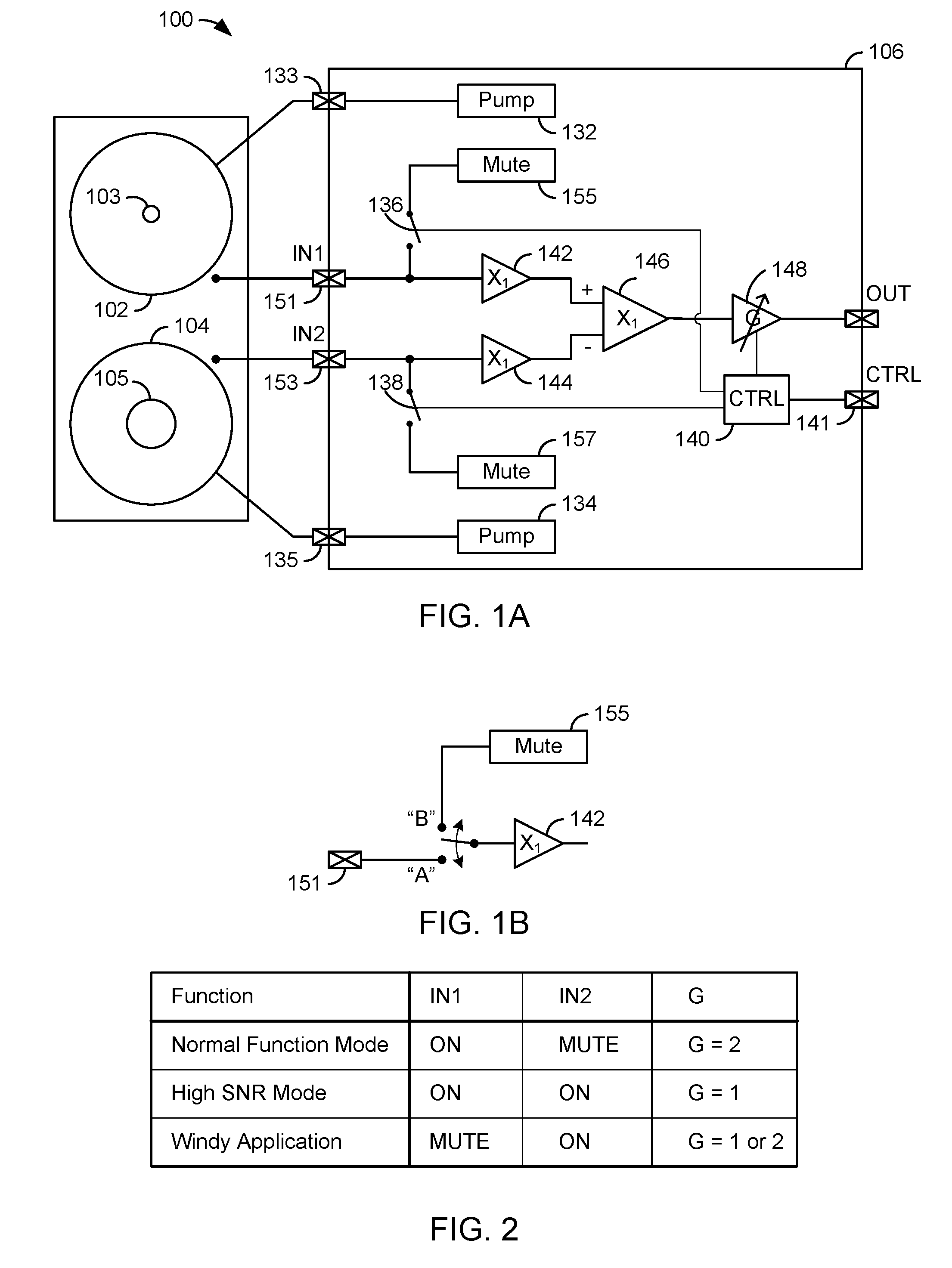
[0016]The present approaches provide two micro electro mechanical system (MEMS) devices. These are sensor devices that convert sound energy into electrical signals. One or more housings can enclose the sensor devices. The housing can have a port (or hole or opening) that extends through the housing so that sound energy can enter the interior. The sound energy can move the diaphragm and with the back plate create an electrical signal that is representative of the sound energy. The first diaphragm has a first pierce hole, (or opening), with a first size and the second diaphragm with a second pierce hole (or opening) with a second size, with the second size being significantly greater than the first size. A controller looks at energy at particular frequencies. If there is a lot of energy (e.g., energy above a predetermined threshold) at low frequencies, it means that there is wind and then the system is operated with the microphone having the large pierce hole or opening. Otherwise, th...


PUM


Abstract

A microphone device is comprises a first micro electro mechanical system (MEMS) device and a second MEMS device with difference size of pierce holes in the diaphragms. Signal outputs from the first and second MEMS devices are selectively used to provide wind noise resistance.

Description

CROSS-REFERENCE TO RELATED APPLICATIONS[0001]This application claims the benefit of and priority to U.S. Provisional Patent Application No. 62 / 196,586, filed Jul. 24, 2015, the entire contents of which are incorporated herein by reference.TECHNICAL FIELD[0002]This application relates to microphones and, more specifically, microphones that provide wind noise resistance.BACKGROUND OF THE INVENTION[0003]Different types of acoustic devices have been used through the years. One type of device is a microphone. In a microelectromechanical system (MEMS) microphone, a MEMS die includes a diagram and a back plate. The MEMS die is supported by a substrate and enclosed by a housing (e.g., a cup or cover with walls). A port may extend through the substrate (for a bottom port device) or through the top of the housing (for a top port device). In any case, sound energy traverses through the port, moves the diaphragm and creates a changing potential with respect to the back plate, which creates an e...

Claims


Application Information

Patent Timeline
IPC IPC(8): H04R17/02
CPCH04R2201/003H04R17/02H04R1/04H04R19/04H04R3/005H04R2410/07H04R19/005H04R1/222
Inventor DAI, WEIWEN
Owner KNOWLES ELECTRONICS INC
Why Eureka
Try Eureka