Clutch control device for four-wheel-drive vehicle

a technology for four-wheel drive vehicles and clutch control devices, which is applied in the direction of mechanical actuated clutches, interlocking clutches, vehicle sub-unit features, etc., can solve the problem of difficulty in reversing the traveling state quickly, and achieve the effect of eliminating the waiting time for reversing the clutch

Active Publication Date: 2017-02-02
NISSAN MOTOR CO LTD
View PDF2 Cites 3 Cited by
  • Summary
  • Abstract
  • Description
  • Claims
  • Application Information

AI Technical Summary

Benefits of technology

[0007]Therefore, in the clutch control device for a four-wheel drive vehicle according to the present invention, the drive mode of the four-wheel drive vehicle is switched by the drive mode switching unit in one of the disconnect two-wheel drive mode, the connect four-wheel drive mode, and the stand-by two-wheel drive mode. Here, when switching from the stand-by two-wheel drive mode to the connect four-wheel drive mode, since the mesh...

Problems solved by technology

Therefore, since switching from 2-wheel drive to the four-wheel drive traveling req...

Method used


Image

  • Clutch control device for four-wheel-drive vehicle
  • Clutch control device for four-wheel-drive vehicle
  • Clutch control device for four-wheel-drive vehicle

Examples


first embodiment

[0019]The clutch control device for a four-wheel drive vehicle of a front wheel drive base (an example of a four-wheel drive vehicle) in accordance with a first embodiment will be described separately in the following sections—“drive system for a four-wheel drive vehicle”, “control system for a four-wheel drive vehicle”, “drive mode switching”, and “drive mode switching process”.

Drive System for a Four-Wheel Drive Vehicle

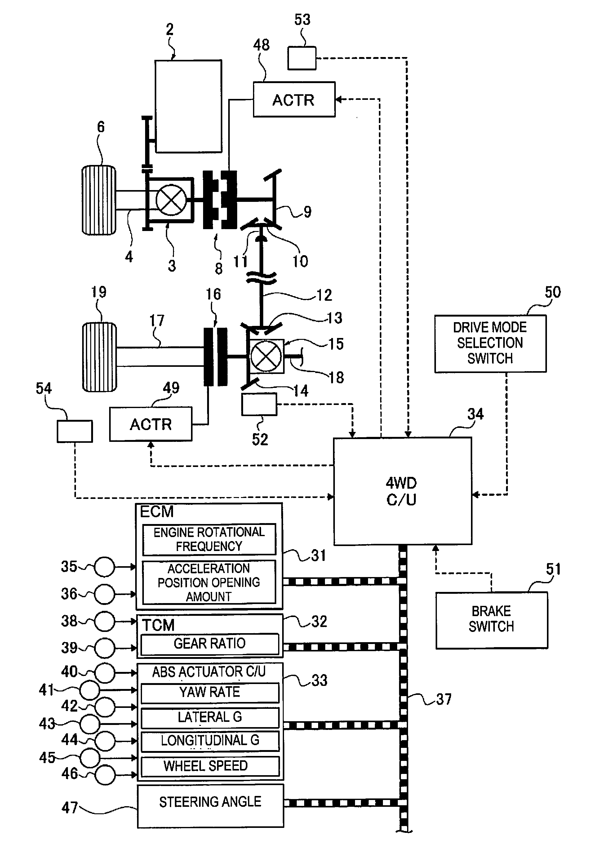
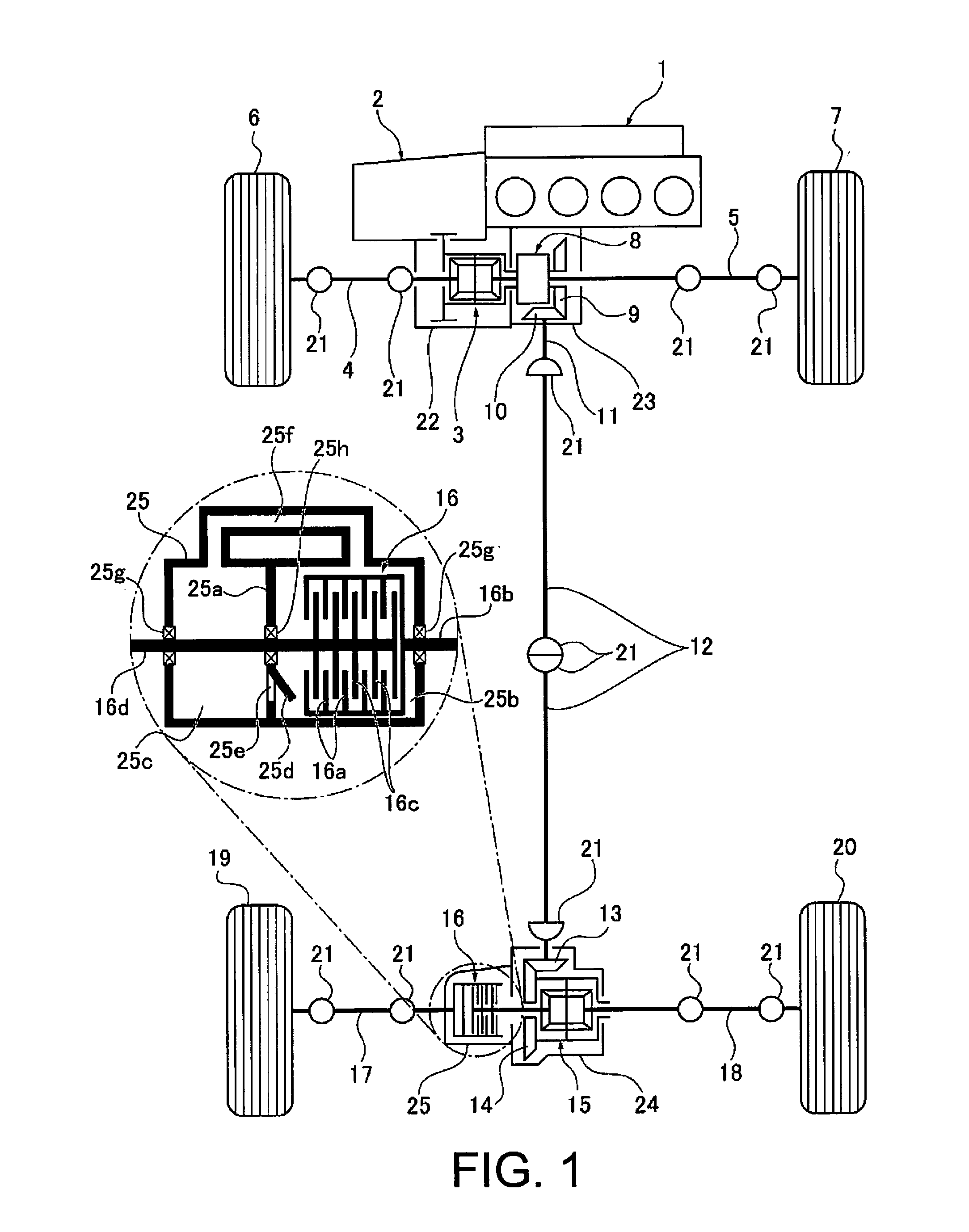
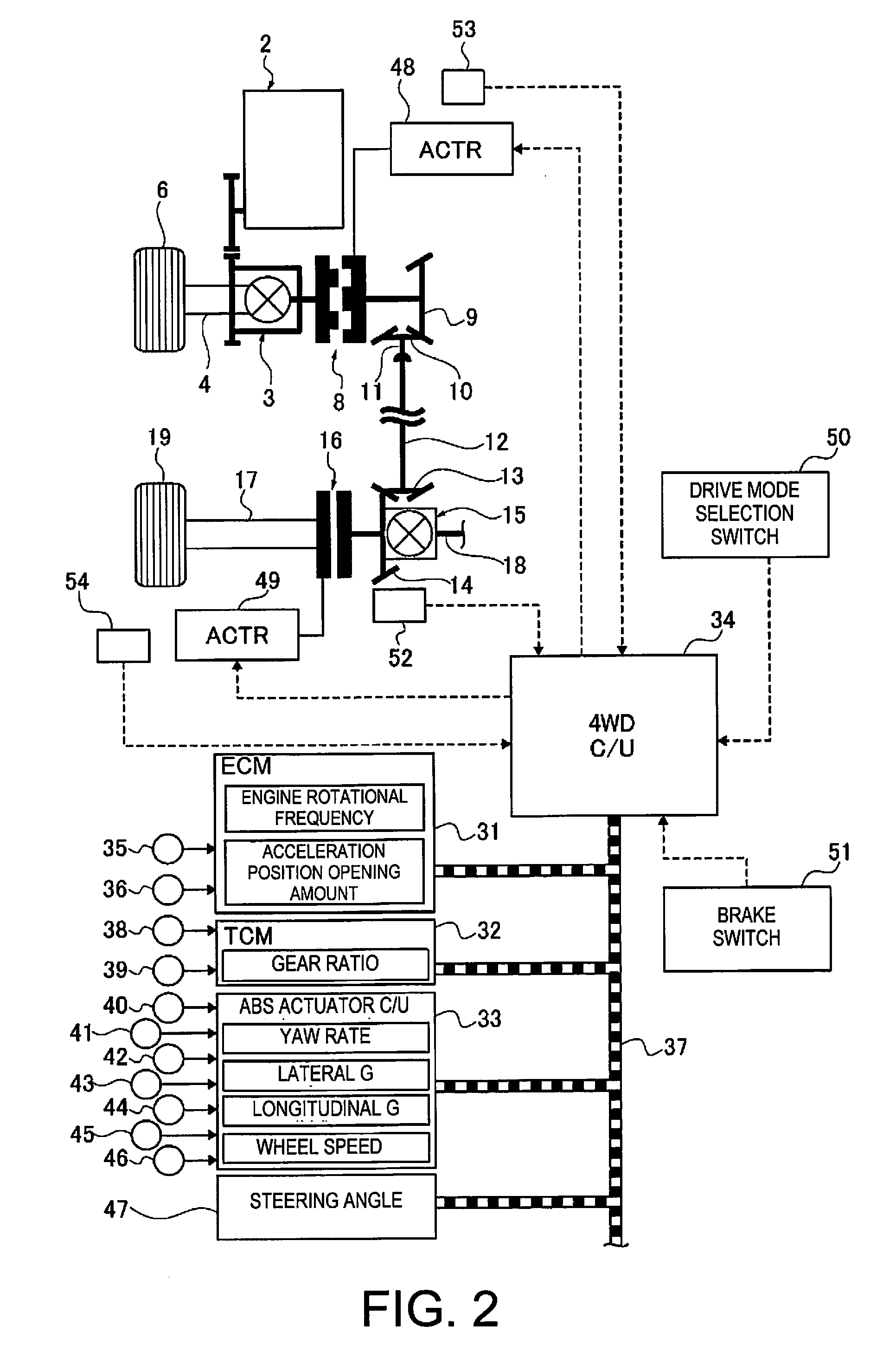
[0020]FIG. 1 schematically illustrates a drive system for a front wheel drive-based four-wheel drive vehicle to which a clutch control device is applied. Below, with reference to FIG. 1, description is given of the drive system configuration of a four-wheel drive vehicle.

[0021]The front wheel drive system for the four-wheel drive vehicle includes, as shown in FIG. 1, a transverse engine 1 (driving source), a transmission 2, a front differential 3, a left front wheel drive shaft 4, a right front wheel drive shaft 5, a left front wheel 6 (main drive wheel), and a righ...

second embodiment

The Second Embodiment

[0124]The second embodiment is an example in which the clutch control device is applied to a four-wheel drive vehicle of the rear wheel drive base and the arrangement of the meshing clutch and the friction clutch with a differential interposed is in a reversed relationship from the first embodiment.

[0125]FIG. 10 schematically illustrates a driving system of a four-wheel drive vehicle with a rear-wheel drive base to which a clutch control device is applied in accordance with a second embodiment. Below, with reference to FIG. 10, a description is given of the drive system configuration of the four-wheel drive vehicle.

[0126]As shown in FIG. 10, the rear wheel drive system of the four wheel drive vehicle includes a longitudinal engine 61 (driving source), a transmission 62, a rear propeller shaft 63, a rear differential 64, a left rear wheel drive shaft 65, a right rear wheel drive shaft 66, a left rear wheel 67 (main drive wheel), and a right rear wheel 68 (main dr...


PUM


Abstract

A vehicle clutch control device is provided for switching from a two-wheel drive traveling to a four-wheel drive traveling. The vehicle clutch control device includes a dog clutch that separates a rear wheel drive from a front wheel drive by releasing the dog clutch, an electronically controlled coupling that distributes a driving force of a transverse engine to left and right rear wheels in accordance with a clutch connection capacity, and a four-wheel drive control unit. The four-wheel drive control unit switches the drive mode to one of a disconnect two-wheel drive mode in which the dog clutch and the electronically controlled coupling are released, a connect four-wheel drive mode in which the dog clutch and the electronically controlled coupling are engaged, and a stand-by two-wheel drive mode in which the dog clutch is engaged while the electronically controlled coupling is released.

Description

CROSS-REFERENCE TO RELATED APPLICATIONS[0001]This application is a U.S. National stage application of International Application No. PCT / JP2015 / 059976, filed Mar. 30, 2015, which claims priority to JP Patent Application No. 2014-082036 filed on Apr. 11 2014, the contents of which are hereby incorporated herein by reference.BACKGROUNDField of the Invention[0002]The present invention generally relates to a clutch control device for a four-wheel drive vehicle equipped with a meshing clutch and a friction clutch in a driving force transmission system to an auxiliary drive wheel.Background Information[0003]Conventionally, a four-wheel drive vehicle of a front wheel drive base is known which is provided with a positive or meshing clutch and a friction clutch in a driving force transmission system (for example, refer to Japanese Laid Open Patent Application No. 2010-254058). In this four-wheel drive vehicle, the meshing clutch and the friction clutch are connected at the time of the 4-wheel...

Claims


Application Information

Patent Timeline
IPC IPC(8): B60K17/02F16D11/00F16D48/06F16D13/74B60K17/344F16D21/00
CPCB60K17/02B60K17/344F16D21/00F16D48/06F16D13/74F16D2500/3144F16D2500/10431F16D2500/3108F16D2500/3115F16D2500/30806F16D2500/31426F16D11/00B60K17/35B60K17/3515B60K23/0808B60K2023/0858B60W2520/10B60W2540/103B60Y2300/427B60Y2300/52B60Y2400/421B60Y2400/424B60Y2400/4244B60K23/08F16D25/0638
Inventor OGAWA, KATSUYOSHIMORI, ATSUHIROMITSUISHI, SHUNICHIMORITA, MAKOTOTAKAISHI, TETSU
Owner NISSAN MOTOR CO LTD
Why Eureka
Try Eureka