Electric parking brake control and method

Active Publication Date: 2017-02-02
FORD GLOBAL TECH LLC
View PDF5 Cites 7 Cited by
  • Summary
  • Abstract
  • Description
  • Claims
  • Application Information

AI Technical Summary

Benefits of technology

The brake control module described in this patent text contains electronic driver stages for controlling the brake actuators via twin-wire lines. The current output can be limited or adjusted via the driver stages with pulse-width modulation. The polarity can be selected for activating or releasing the brake shoes. The actuators of the parking brake can act on the rear-wheel axle and the braking force applied by the actuators can be limited to avoid rear-wheel axle lockup. The detection of a beginning brake-pedal actuation can be made based on even slight contact of the brake pedal or a sudden release of the gas pedal. The level of confidence in pre-energization activation can be based on a weighing between carrying out the pre-energization as soon as possible and carrying out it without actual braking. The position of the parking brake actuators can be estimated based on the current uptake of the motors or a dedicated position sensor can be provided.

Problems solved by technology

If the electric braking-force support failed, enough service-brake force through the hydraulic brake system is not always ensured, since with electrically supported brake systems, relatively low-volume tandem main cylinders are often used, which may not be capable of providing enough hydraulic fluid if failure of the electrical support occurs and manual actuation.
Independently thereof, if failure of the braking-force support occurs, the pedal travel and pedal forces increase, which can cause the driver of the vehicle ultimately applying insufficient braking forces.

Method used


Image

  • Electric parking brake control and method
  • Electric parking brake control and method

Examples


Embodiment Construction

[0016]The following description of the preferred embodiment(s) is merely exemplary in nature and is in no way intended to limit the invention, its application, or uses.

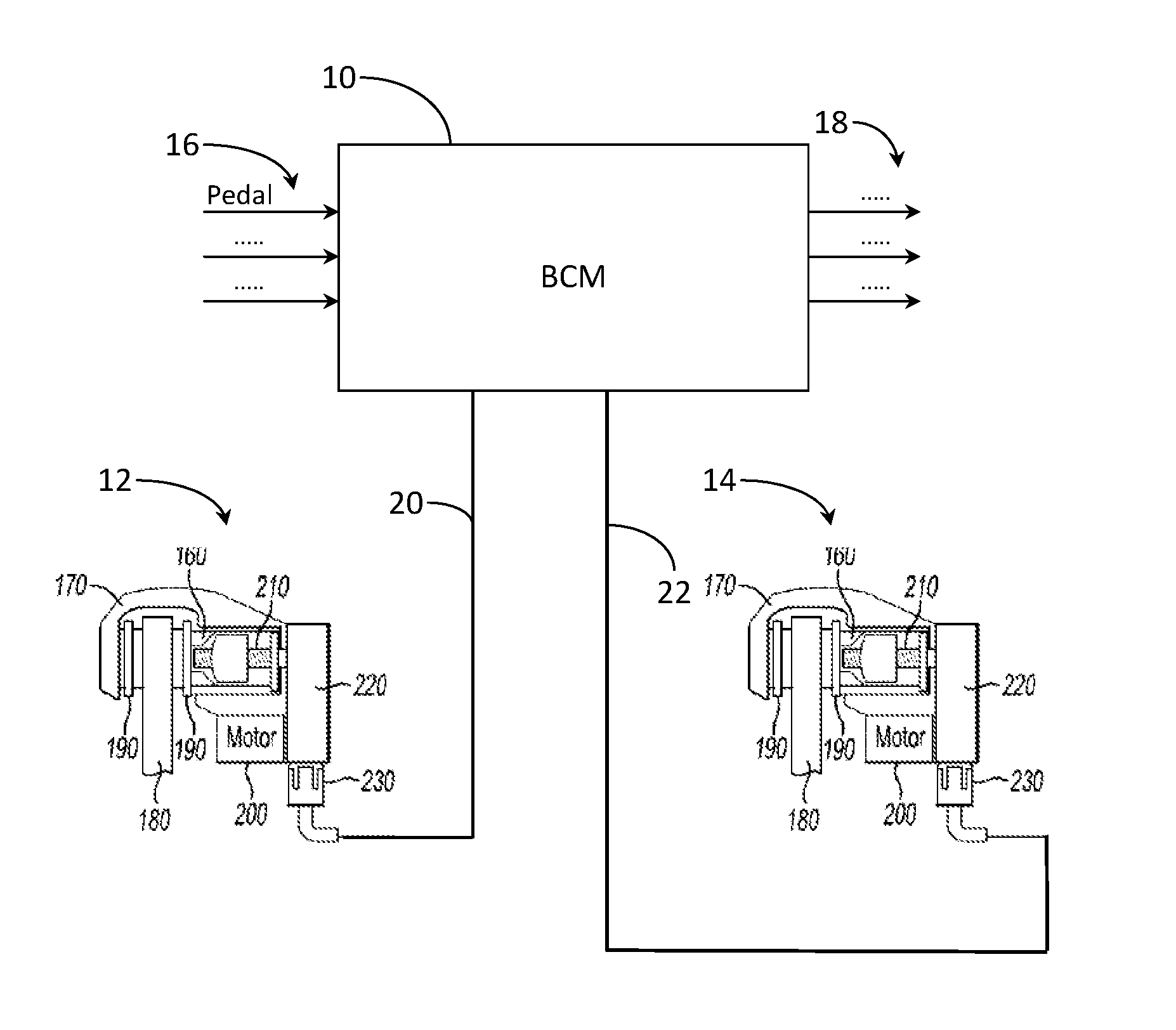
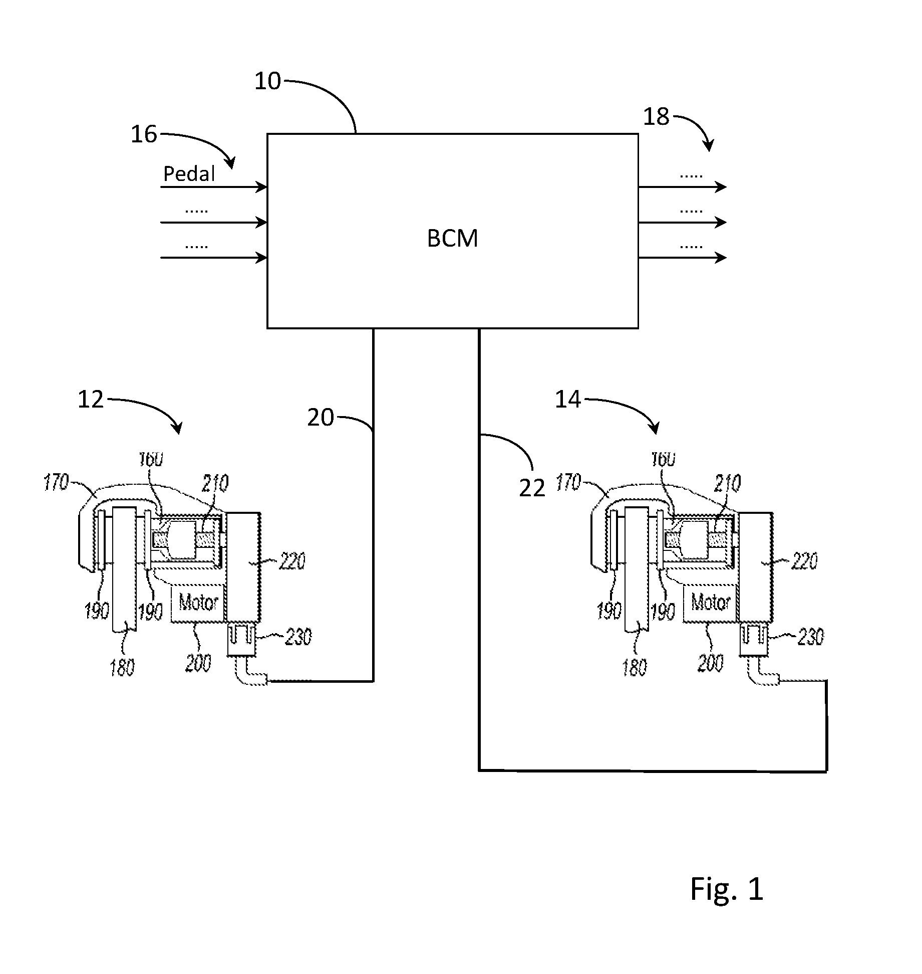
[0017]The brake control module 10 receives, via inputs 16, a plurality of input signals, including for example a brake pedal sensor signal, and transmits, via outputs 18, a plurality of control signals for controlling an electric brake booster for a hydraulic service brake (not shown).

[0018]In addition, the brake control module contains electronic driver stages for controlling the brake actuators 12 and 14 via the twin-wire lines 20, 22. The current output at the commutator-direct current motors can be limited or adjusted via the driver stages with pulse-width modulation. Furthermore, the polarity can be selected for implementing an activation or release of the brake shoes. In the present example, the parking brake is used as an additional service brake depending on the brake command of a brake pedal. Upon detection o...


PUM


Abstract

A method for controlling an electric parking brake for a motor vehicle including a brake actuator having an electric motor disposed directly on the brake caliper. When the parking brake is utilized as an additional service brake, depending on a brake pedal brake command, the electric motor is initially energized on detection of an imminent or commencing brake-pedal actuation however the electric motor generates no braking force until a predetermined or specific brake command is received. As a result, an overload of the vehicle voltage source is avoided if simultaneous utilization of multiple parking-brake actuators occurs.

Description

CROSS-REFERENCE TO RELATED APPLICATIONS[0001]Not Applicable.BACKGROUND OF THE INVENTION[0002]1. Field of the Invention[0003]An electric parking brake for a motor vehicle, and more specifically, a parking brake used as an additional service brake for vehicle deceleration.[0004]2. Description of Related Art[0005]In the field of motor vehicles, electric parking brakes are increasingly replacing conventional brake-cable parking brakes. Besides various advantages—like saving space regarding the operating elements and eliminating the brake cables—electrically controlled parking brakes can also be automatically activated and deactivated by an engine control unit independently of operator action and can also carry out other functions—like an automatic anti-roll-back device—during active vehicle operation.[0006]It is known to use the parking brake as an additional service brake in certain situations in which the braking forces applied by the regular service brake are insufficient, e.g., if a...

Claims


Application Information

Patent Timeline
IPC IPC(8): B60T13/74B60T8/172B60T8/1761B60T7/04
CPCB60T13/741B60T8/1761B60T8/172B60T7/042B60T2201/03B60T8/17616B60T13/586B60T13/662B60T17/22B60T2270/402
Inventor SUERMANN, MARCTRAPPE, JILLDANIELS, RUDOLFSVENSSON, THOMAS
Owner FORD GLOBAL TECH LLC
Why Eureka
Try Eureka