Stator for rotating electric machine

Active Publication Date: 2017-02-02
DENSO CORP
View PDF2 Cites 38 Cited by
  • Summary
  • Abstract
  • Description
  • Claims
  • Application Information

AI Technical Summary

Benefits of technology

[0014]With the above arrangement, it becomes possible to reduce the potential difference to ground, thereby preventi

Problems solved by technology

However, at the same time, distributed winding has a disadvantage such that the distance between each circumferentially-adjacent pair

Method used


Image

  • Stator for rotating electric machine
  • Stator for rotating electric machine
  • Stator for rotating electric machine

Examples


first embodiment

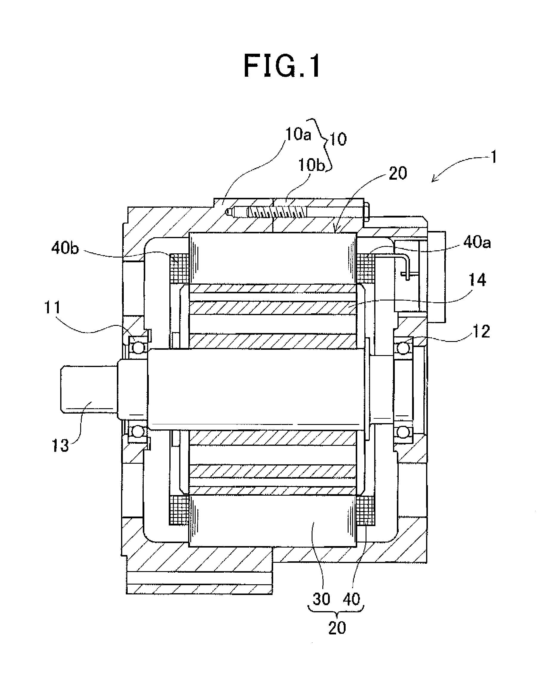
[0059]FIG. 1 shows the overall configuration of a rotating electric machine 1 according to a first embodiment.

[0060]The rotating electric machine 1 is designed to be used in a motor vehicle, such as a passenger car or truck, as an electric motor.

[0061]As shown in FIG. 1, the rotating electric machine 1 includes a housing 10, a rotor 14 and a stator 20. The housing 10 is comprised of a pair of cup-shaped housing pieces 10a and 10b which are jointed together at the open ends thereof. The housing 10 has a pair of bearings 11 and 12 mounted therein, via which a rotating shaft 13 is rotatably supported by the housing 10. The rotor 14 is received in the housing 10 and fixed on the rotating shaft 13. The stator 20 is fixed in the housing 10 so as to surround the radially outer periphery of the rotor 14.

[0062]The rotor 14 has a plurality of permanent magnets embedded at predetermined positions therein. The permanent magnets form a plurality of magnetic poles on the radially outer periphery ...

second embodiment

[0174]A stator 20A according to a second embodiment has almost the same structure as the stator 20 according to the first embodiment. Accordingly, only the differences therebetween will be described hereinafter.

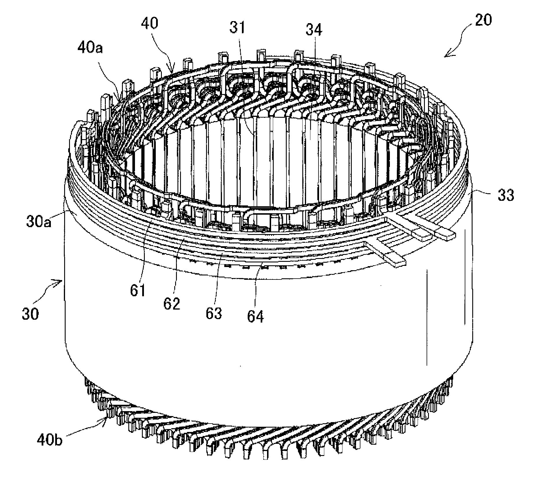
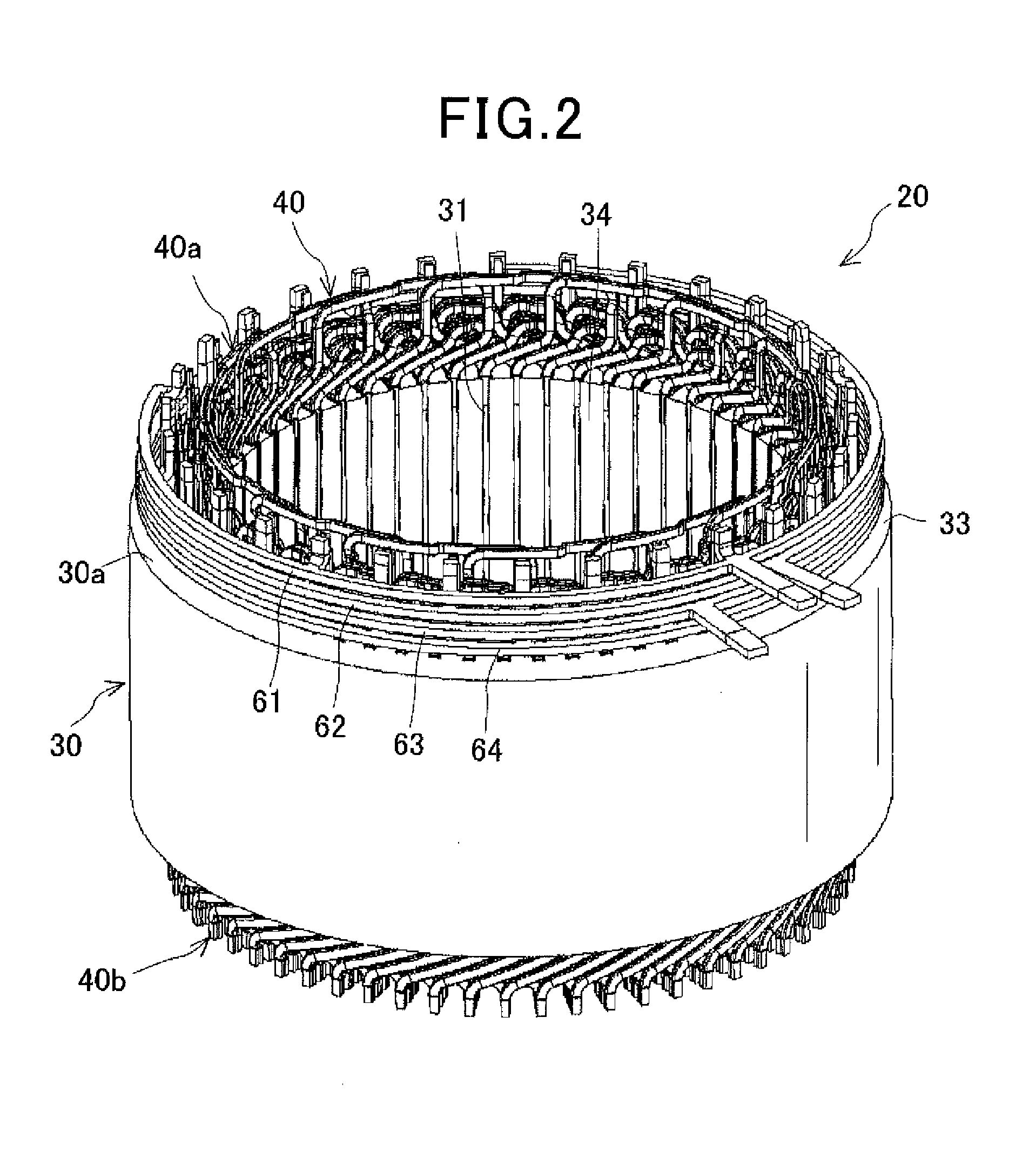
[0175]As shown in FIGS. 36 and 37, in the stator 20A according to the present embodiment, the U-phase, V-phase, W-phase and neutral busbars 61-64 are integrated by a resin member 66 into one piece. In other words, the U-phase, V-phase, W-phase and neutral busbars 61-64 and the resin member 66 together form one integrated body.

[0176]In addition, as in the first embodiment, the U-phase, V-phase, W-phase and neutral busbars 61-64 are located axially outside the stator core 30 and radially outside the first coil end part 40a of the stator coil 40. The U-phase, V-phase, W-phase and neutral busbars 61-64 are axially aligned with each other. Among the U-phase, V-phase, W-phase and neutral busbars 61-64, the neutral busbar 64, which has the lowest electric potential, is located close...

first modification

[First Modification]

[0181]In this modification, as shown in FIG. 38, the resin member 66 is formed by multi-phase (or multi-shot) molding to include three segments 66A, 66B and 66B.

[0182]Moreover, a boundary between the segments 66A and 66B of the resin member 66 is located on that side surface of the resin member 66 which faces and abuts the first axial end face 30a of the stator core 30.

[0183]With the above arrangement, a ground fault may occur between the busbars 61-64 and the stator core 30 through the boundary between the segments 66A and 66B of the resin member 66. However, in the present modification, among the busbars 61-64, the neutral busbar 64, which has the lowest electric potential, is located closest to the stator core 30. Consequently, though the boundary between the segments 66A and 66B of the resin member 66 is located on the side surface of the resin member 66, it is still possible to reliably prevent a ground fault from occurring between the busbars 61-64 and the ...


PUM


Abstract

A stator includes a stator core having slots, a stator coil comprised of three phase windings, phase busbars each electrically connecting a corresponding one of the phase windings to an inverter, and a neutral busbar star-connecting the phase windings to define a neutral point therebetween. In each of the slots of the stator core, there are arranged K in-slot portions of the phase windings of the stator coil in K layers so as to be radially aligned with each other, where K is an even number. The phase and neutral busbars are electrically connected with those in-slot portions of the phase windings of the stator coil which are arranged at the radially outermost layer or the radially innermost layer in the respective slots of the stator core so as to be circumferentially spaced from one another by M slot-pitches or more, where M is a slot multiplier number.

Description

CROSS-REFERENCE TO RELATED APPLICATION[0001]This application is based on and claims priority from Japanese Patent Application No. 2015-152831 filed on Jul. 31, 2015, the content of which is hereby incorporated by reference in its entirety into this application.BACKGROUND[0002]1. Technical Field[0003]The present invention relates to stators for rotating electric machines that are used in, for example, motor vehicles as electric motors and electric generators.[0004]2. Description of Related Art[0005]There are known rotating electric machines that are used in motor vehicles as electric motors and electric generators. These rotating electric machines generally include a rotor and a stator. The rotor is rotatably provided and functions as a field. The stator is disposed in radial opposition to the rotor and functions as an armature.[0006]Japanese Patent Application Publication No. JP2013162636A discloses a stator for a rotating electric machine. The stator is formed by assembling a plura...

Claims


Application Information

Patent Timeline
IPC IPC(8): H02K3/12H02K3/30H02K3/18H02K1/14H02K1/16
CPCH02K3/12H02K1/146H02K3/30H02K3/18H02K1/165H02K3/28H02K3/521H02K3/52
Inventor TAMURA, AKITO
Owner DENSO CORP
Why Eureka
Try Eureka