Heat exchanger

a heat exchanger and heat dissipation technology, applied in indirect heat exchangers, lighting and heating apparatus, transportation and packaging, etc., can solve the problems of insufficient storage of cold heat in the heat storage body, large heat dissipation resistance, etc., and achieve the effect of reducing heat dissipation resistan

Active Publication Date: 2017-02-09
DENSO CORP
View PDF12 Cites 2 Cited by
  • Summary
  • Abstract
  • Description
  • Claims
  • Application Information

AI Technical Summary

Benefits of technology

[0014]A heat can be transferred from the heat storage body directly to the first passage, i.e., the heat transfer target, in the heat dissipation since a case to house the heat storage body is not necessary. As a result, there is no heat resistance between the heat storage body and the case and between the case and the second passage in the heat dissipation. The heat resistance thereby can be reduced when the heat storage body dissipates heat to the heat transfer target.

Problems solved by technology

As a result, the thermal resistance in the heat dissipation may become large in an entirety of the heat exchanger.
As a result, the heat storage body may not be able to store cold heat sufficiently.

Method used


Image

  • Heat exchanger
  • Heat exchanger
  • Heat exchanger

Examples


first embodiment

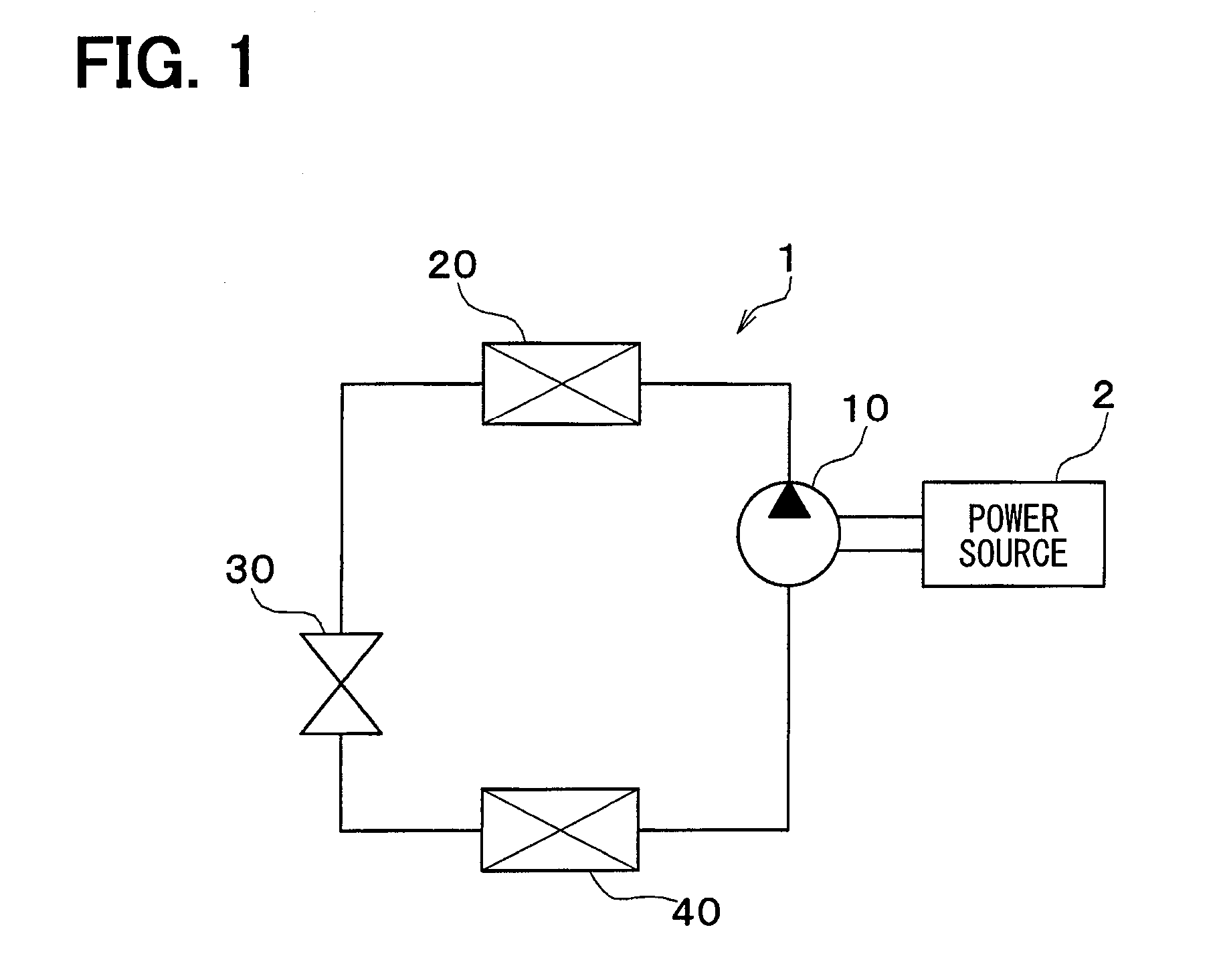
[0022]A first embodiment will be described hereafter referring to FIG. 1 through FIG. 4. FIG. 1 shows a configuration of a refrigeration cycle device configuring a vehicle air conditioner. The refrigeration cycle device 1 configuring the vehicle air conditioner has a compressor 1, a radiator 20, a pressure reducer 30, and an evaporation device (i.e., an evaporator) 40. The components are connected to each other in a circle by a pipe and configure a refrigerant circulation passage.

[0023]The compressor 10 is driven by an internal combustion engine (or a device such as an electric motor) that is a power source 2 for moving a vehicle. The compressor 10 is stopped when the power source 2 is stopped. The compressor 10 draws refrigerant from the evaporator 40 and discharges the refrigerant to the radiator 20 after compressing the refrigerant. The radiator 20 cools a high-temperature refrigerant. The radiator 20 is also referred to as a condenser. The pressure reducer 30 reduces a pressure ...

second embodiment

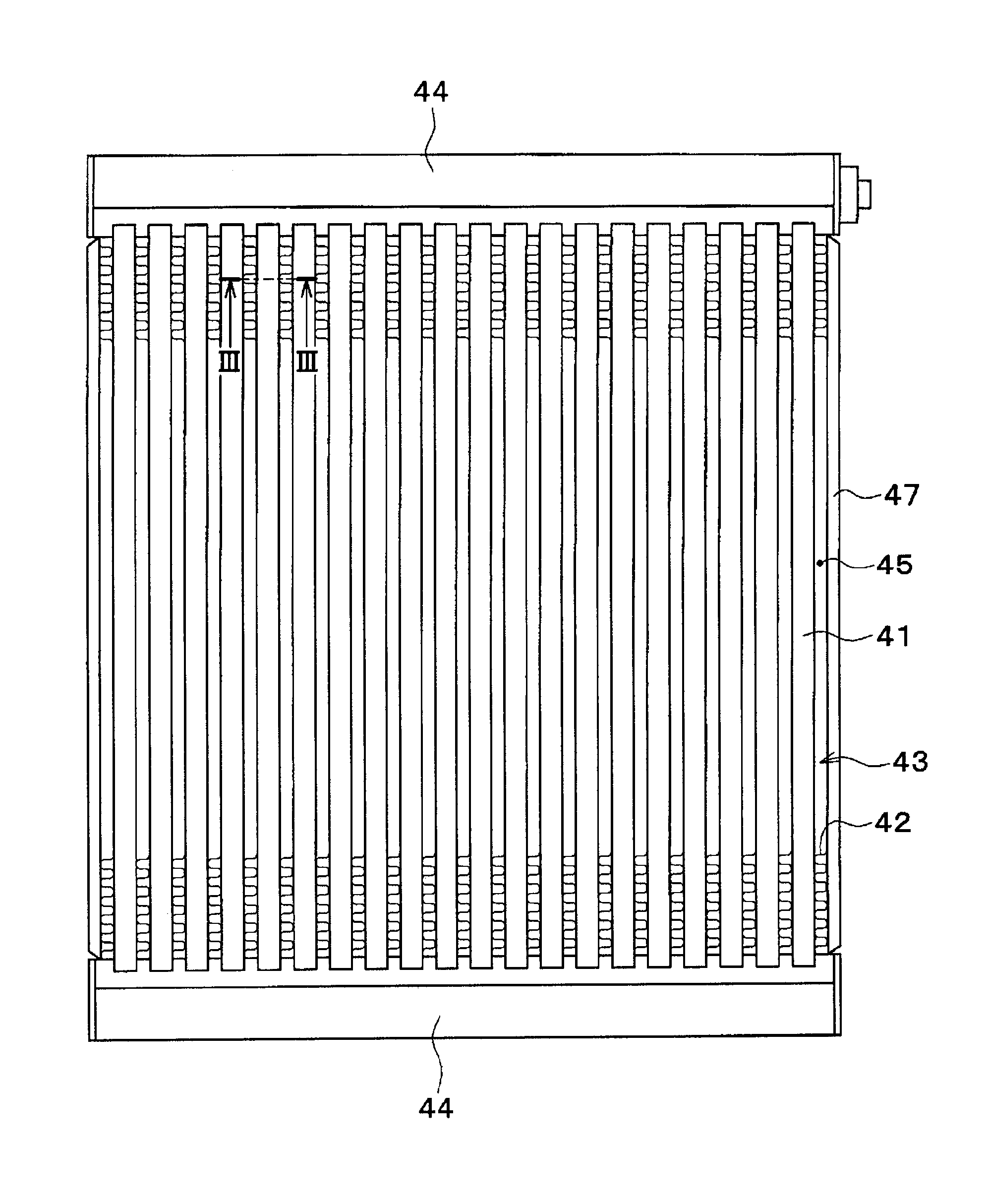
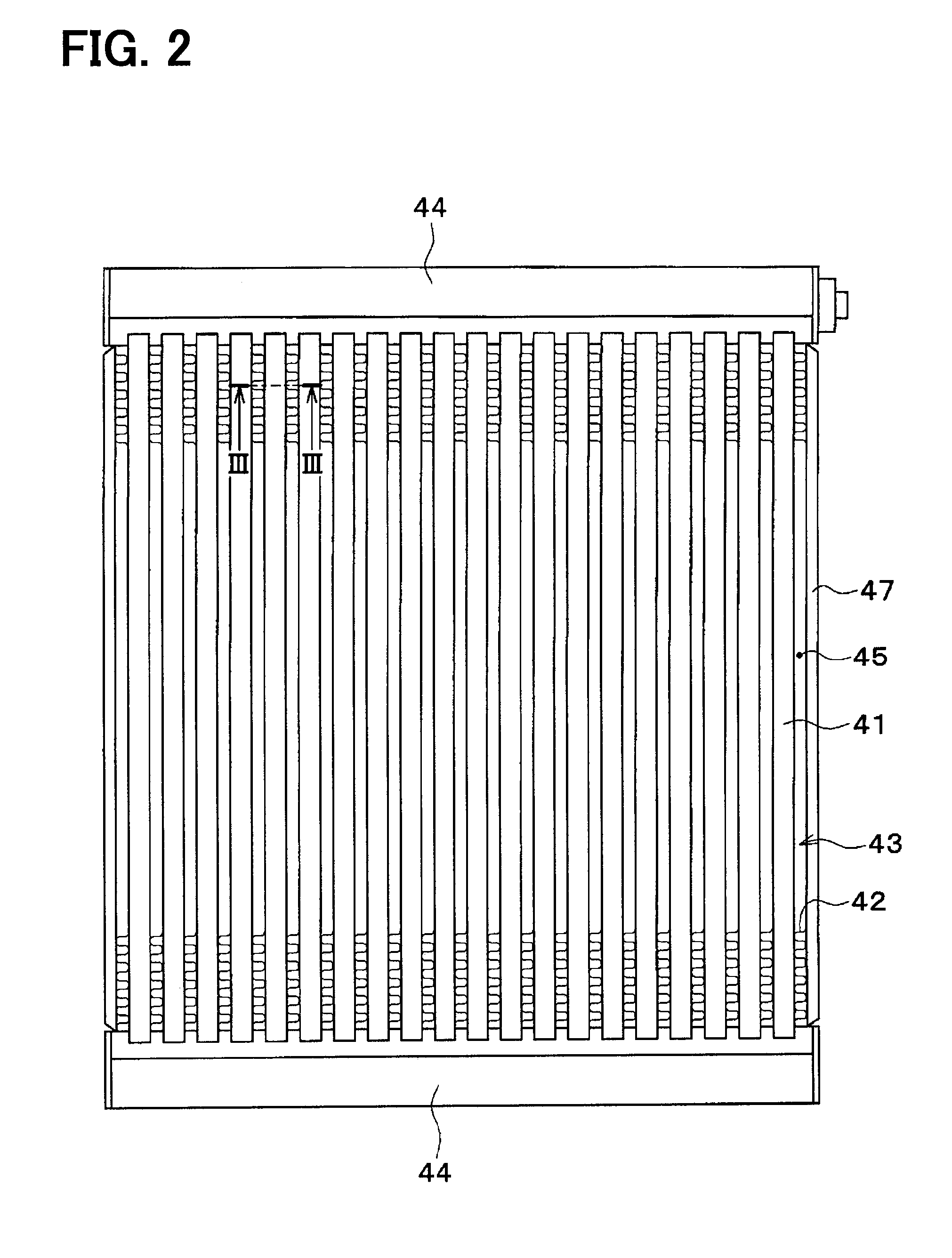
[0047]A second embodiment of the present disclosure will be described hereafter referring to FIG. 5. As shown in FIG. 5, the air passage 45 of the present embodiment is formed integrally with the heat storage body 41. That is, both the refrigeration passage 46 and the air passage 45 are formed in the heat storage body 41 integrally with the heat storage body 41. Specifically, both the refrigeration passage 46 and the air passage 45 are formed in the heat storage body 41 integrally with the heat storage body 41 by providing a through-hole for the refrigeration passage 46 and a through-hole for the air passage 45 in the heat storage body 41.

[0048]Other configuration is the same as that of the first embodiment. According to the evaporator 40 of the present embodiment, a similar effect as the first embodiment can be acquired.

Other Modifications

[0049]It should be understood that the present disclosure is not limited to the above-described embodiments and intended to cover various modific...


PUM

PropertyMeasurementUnit
temperatureaaaaaaaaaa
phase transition temperatureaaaaaaaaaa
phase transitionaaaaaaaaaa

Abstract

A heat exchanger has (i) a first passage in which a first fluid flows, (ii) a heat storage body that is thermally connected to the first passage and stores a warm heat or a cold heat, and (iii) a second passage that is thermally connected to both of the first passage and the heat storage body, the second passage in which a second fluid flows. The heat storage body changes to a first phase in a solid state when a temperature of the heat storage body is lower than or equal to a phase transition temperature, and changes to a second phase in a solid state when the temperature of the heat storage body exceeds the phase transition temperature. The heat storage body stores or dissipates heat depending on a phase transition between the first phase and the second phase.

Description

CROSS REFERENCE TO RELATED APPLICATION[0001]This application is based on Japanese Patent Application No. 2014-106784 filed on May 23, 2014, the disclosure of which is incorporated herein by reference.TECHNICAL FIELD[0002]The present disclosure relates to a heat exchanger applied to a cold heat exchanger for a refrigeration cycle.BACKGROUND ART[0003]Conventionally, a refrigeration cycle is used in an air conditioner. It is considered to perform a specific cooling operation on a condition that the refrigeration cycle is stopped. For example, a compressor in the refrigeration cycle is driven by an engine for moving a vehicle in a vehicle air conditioner. The refrigeration cycle is thereby stopped when the engine is stopped while the vehicle is stopping moving temporarily.[0004]For a purpose of performing a specific cooling operation while the vehicle is stopping moving, it is disclosed that a heat exchanger has a cold heat storage body storing a cold heat in an evaporator disposed in t...

Claims


Application Information

Patent Timeline
Patent Type & Authority Applications(United States)
IPC IPC(8): B60H1/00C09K5/06C01G41/00B60H1/32
CPCB60H1/005B60H1/3204C01P2006/34C09K5/066C01G41/006B60H1/00335F28D1/05383F28D20/0056F28D20/025F28D2020/0013F28D2021/0068F28D2021/0085Y02E60/14
Inventor FUSE, TAKUYAKONO, YASUSHIKASAMATSU, SHINYA
Owner DENSO CORP
Why Eureka
Try Eureka