Wireless sensor and method of interrogating thereof

a wireless sensor and sensor array technology, applied in the field of resonance sensors, can solve the problems of increasing the size of the sensor, increasing the cost of manufacturing and providing the sensors for the sensor array, and challenging to differentiate the response of each resonance sensor

Active Publication Date: 2017-02-09
GENERAL ELECTRIC CO
View PDF1 Cites 3 Cited by
  • Summary
  • Abstract
  • Description
  • Claims
  • Application Information

AI Technical Summary

Problems solved by technology

While use of a single resonant sensor raises no issues with regard to interrogation of the sensor and readout of the sensor via an associated receiver, it is recognized that issues arise when a sensor array composed of a large number of resonant sensors (e.g., 1000+ sensors) in close proximity to one another are to be interrogated and read out.
That is, it is challenging to differentiate the response from each resonant sensor from the other proximate sensors such that the reado

Method used


Image

  • Wireless sensor and method of interrogating thereof
  • Wireless sensor and method of interrogating thereof
  • Wireless sensor and method of interrogating thereof

Examples


Embodiment Construction

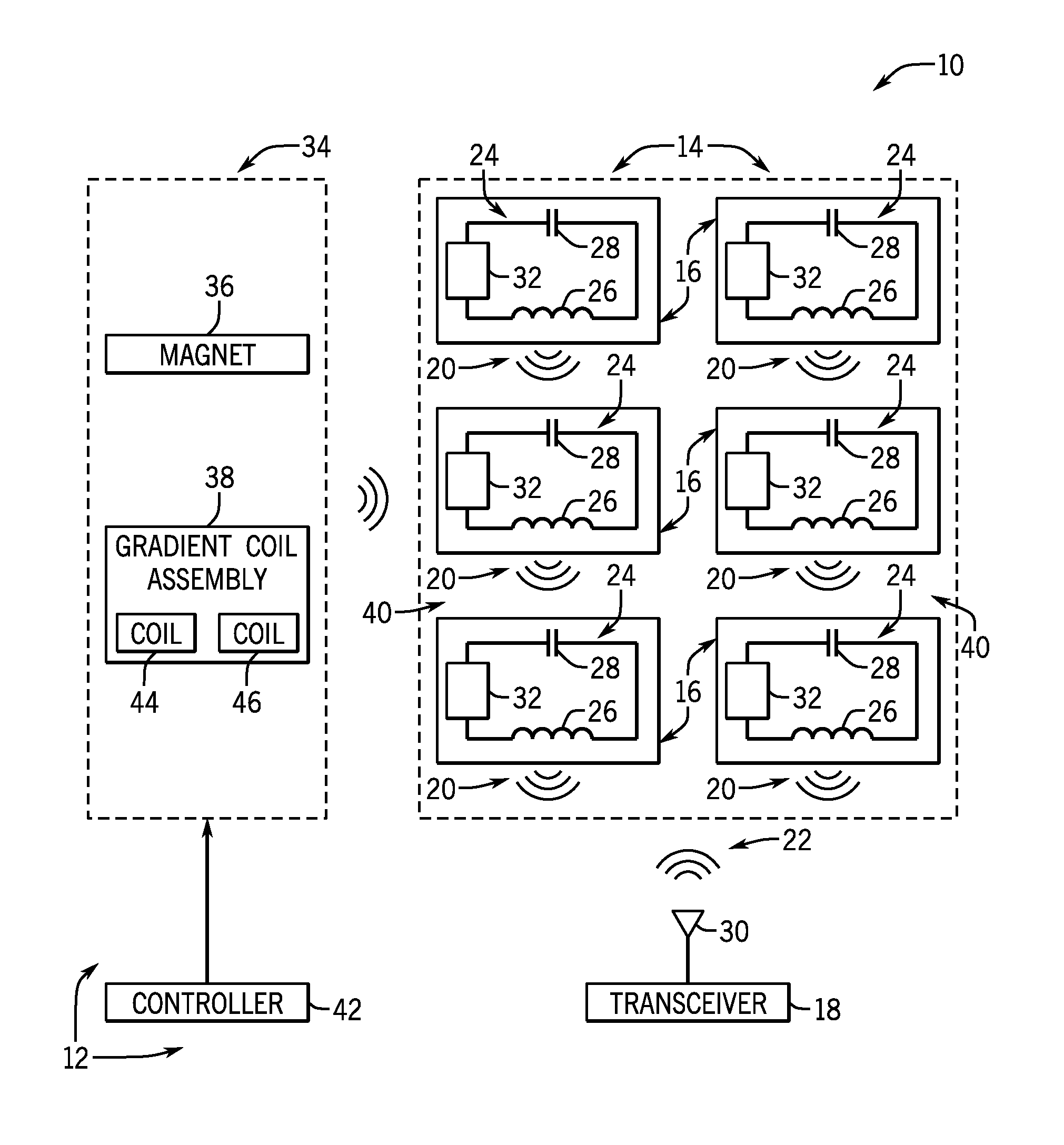
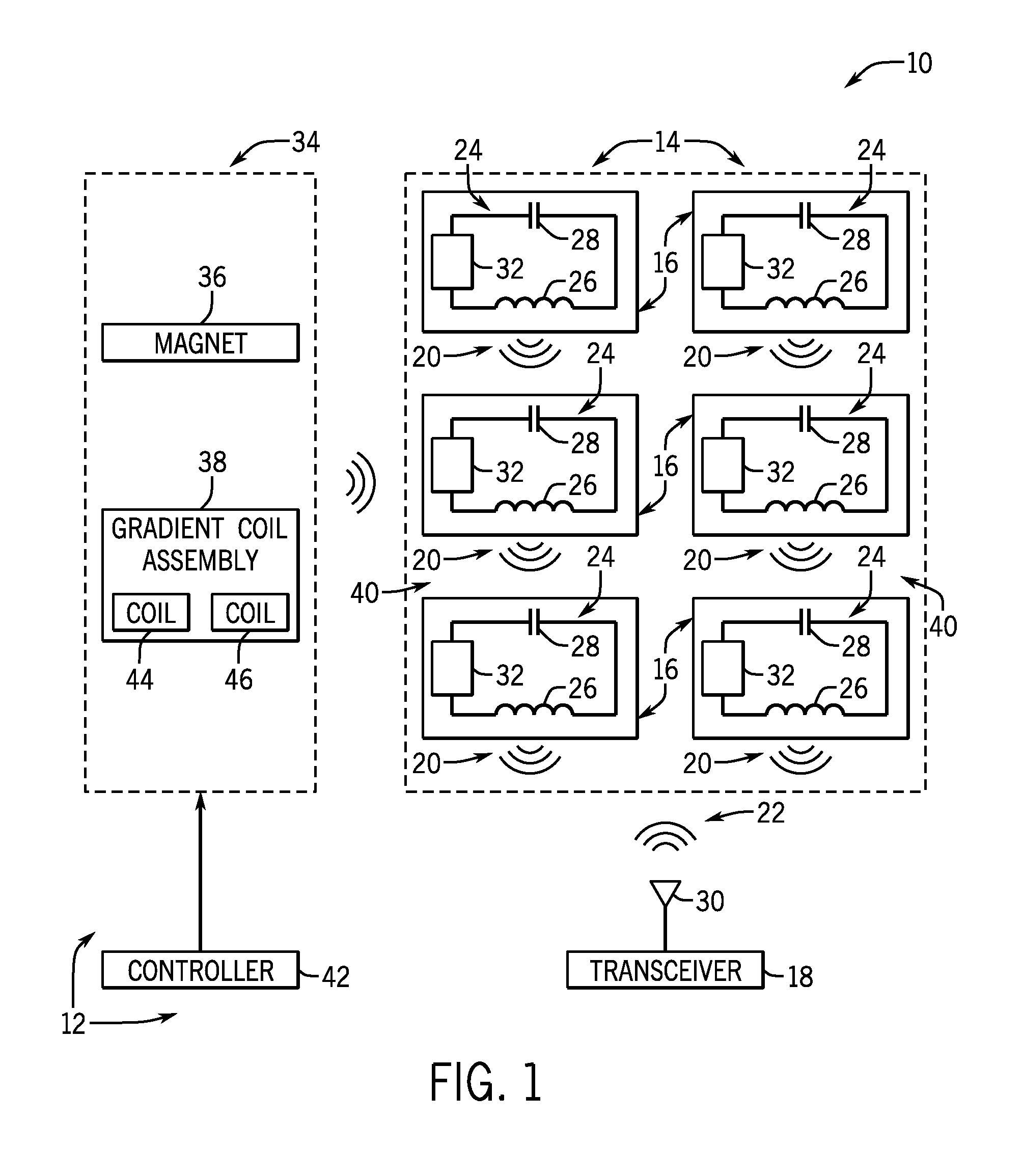
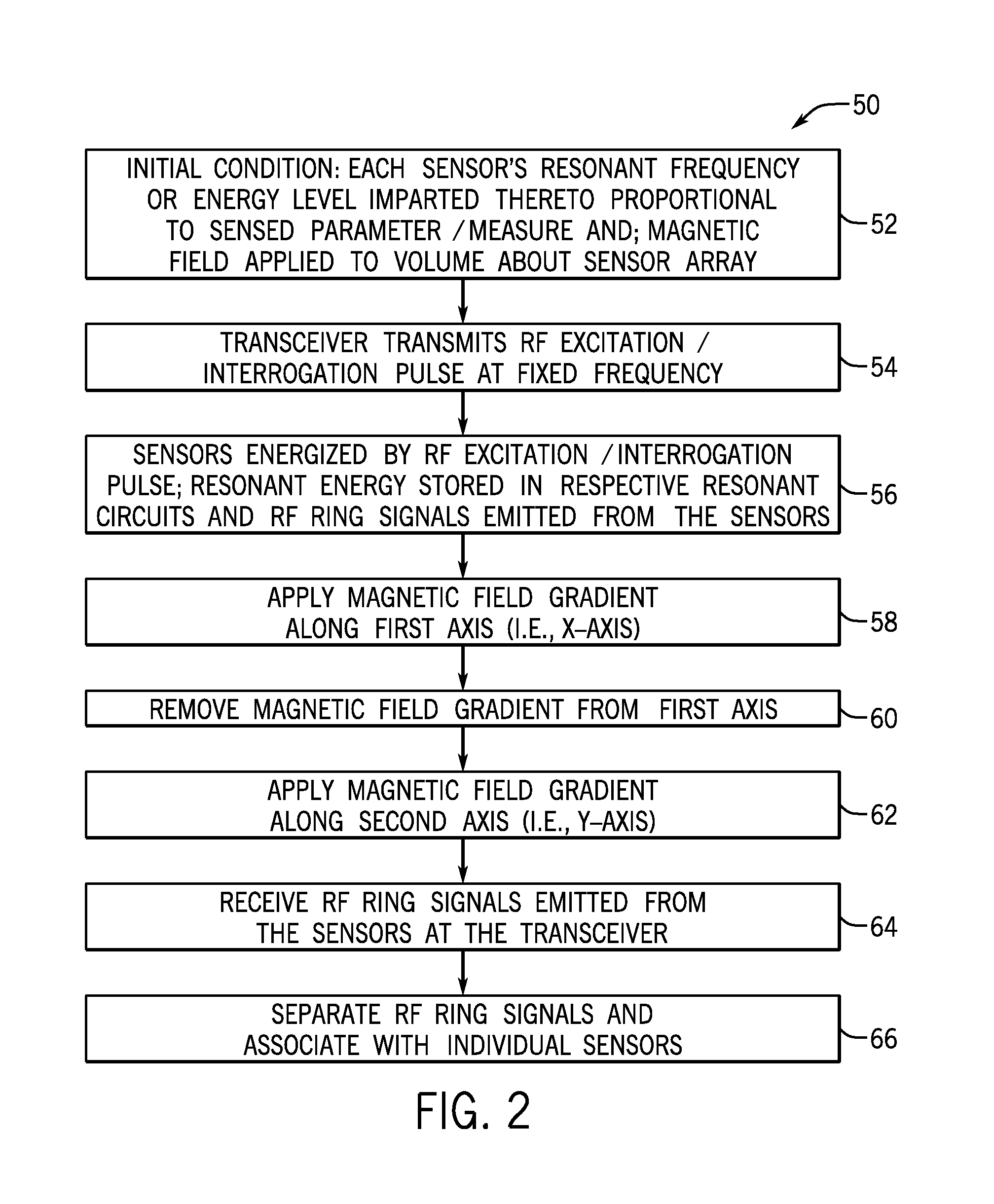
[0014]Embodiments of the invention provide an array of resonant sensors that may be interrogated via the use of a combination of RF pulses and a magnetic field gradient being applied thereto. The interrogation of the array of sensors using the combination of RF pulses and the magnetic field gradient results in each resonant sensor emitting a unique phase and frequency pair based on its positioning within the magnetic field, so as to enable the reading of each sensor to be separated at a receiver.

[0015]Referring now to FIG. 1, a block schematic diagram of a passive wireless sensor array communication system 10 is shown according to an embodiment of the invention. The communication system 10 includes a sensor interrogator system 12 and a sensor array 14 comprised of a plurality of wireless sensors 16 that are provided for sensing a specific parameter or measurand—with examples of such parameters being neural activity, pressure, temperature, acceleration, angular rate, PH level, glucos...


PUM


Abstract

A wireless sensor array communication system includes a plurality of wireless sensors each including a resonant circuit that is excited by an RF pulse so as to provide a resonant energy proportional to a measurand being monitored. A transceiver of an interrogator system transmits RF pulses to each of the sensors to excite the resonant circuits therein and receives RF signals transmitted from each of the sensors that are indicative of the resonant energy provided by the resonant circuit. A magnet-gradient coil arrangement of the interrogator system generates a magnetic field and selectively applies magnetic field gradients along a number of axes, such that a frequency and phase of the resonant energy provided by the resonant circuit of each wireless sensor is altered responsive thereto, with the altered frequency and phase of the resonant energy being a function of a location of the respective wireless sensor within the magnetic field.

Description

BACKGROUND OF THE INVENTION[0001]Embodiments of the invention relate generally to resonant sensors and, in particular, to resonant sensors that may be interrogated via the use of a combination of RF pulses and a magnetic field gradient being applied thereto, such that a resonant sensor will emit a unique phase and frequency pair based on it's positioning within the magnetic field.[0002]Resonant sensors are sensors whose output can vary with respect to changes in specific environmental or biological conditions present near the resonant sensor. Typically, resonant sensors are comprised of an inductance-capacitance (LC) circuit with a specific resonance frequency. The resonant sensor is excited by an RF pulse and then its value can be read back by the amount of energy they emit as the LC circuit's resonant energy decays. In use, the amount of energy imparted into the resonant circuit can be proportional to the measurand (i.e., the object / substance being measured) and / or the frequency o...

Claims


Application Information

Patent Timeline
IPC IPC(8): G01N27/02
CPCG01N27/023G01R33/00G01R33/022G01D21/00
Inventor SEXTON, DANIEL WHITE
Owner GENERAL ELECTRIC CO
Why Eureka
Try Eureka