High Current Limit Trim Apparatus and Methodology

a technology of current limit and trim apparatus, which is applied in the direction of electronic circuit testing, electronic protection circuit testing, instruments, etc., can solve the problems of high transient demands of certain electronically-driven power devices, stress, damage, fault violations of power driving circuitry, etc., and achieves hardware and reliability requirements of test equipment for production. high, the effect of high reliability

Active Publication Date: 2017-02-09
TEXAS INSTR INC
View PDF5 Cites 6 Cited by
  • Summary
  • Abstract
  • Description
  • Claims
  • Application Information

AI Technical Summary

Problems solved by technology

Certain electronically-driven power devices have high transient demands, such as at cold start-up, which tend toward requiring high current flow to meet the device (or customer) demands.
High current flow can cause stress, damage, and fault violations to power driving circuitry, including one or more FETs.
However, due to certain factors, such as process variations and mismatch of devices, the current threshold needs to be set or

Method used


Image

  • High Current Limit Trim Apparatus and Methodology
  • High Current Limit Trim Apparatus and Methodology
  • High Current Limit Trim Apparatus and Methodology

Examples


Embodiment Construction

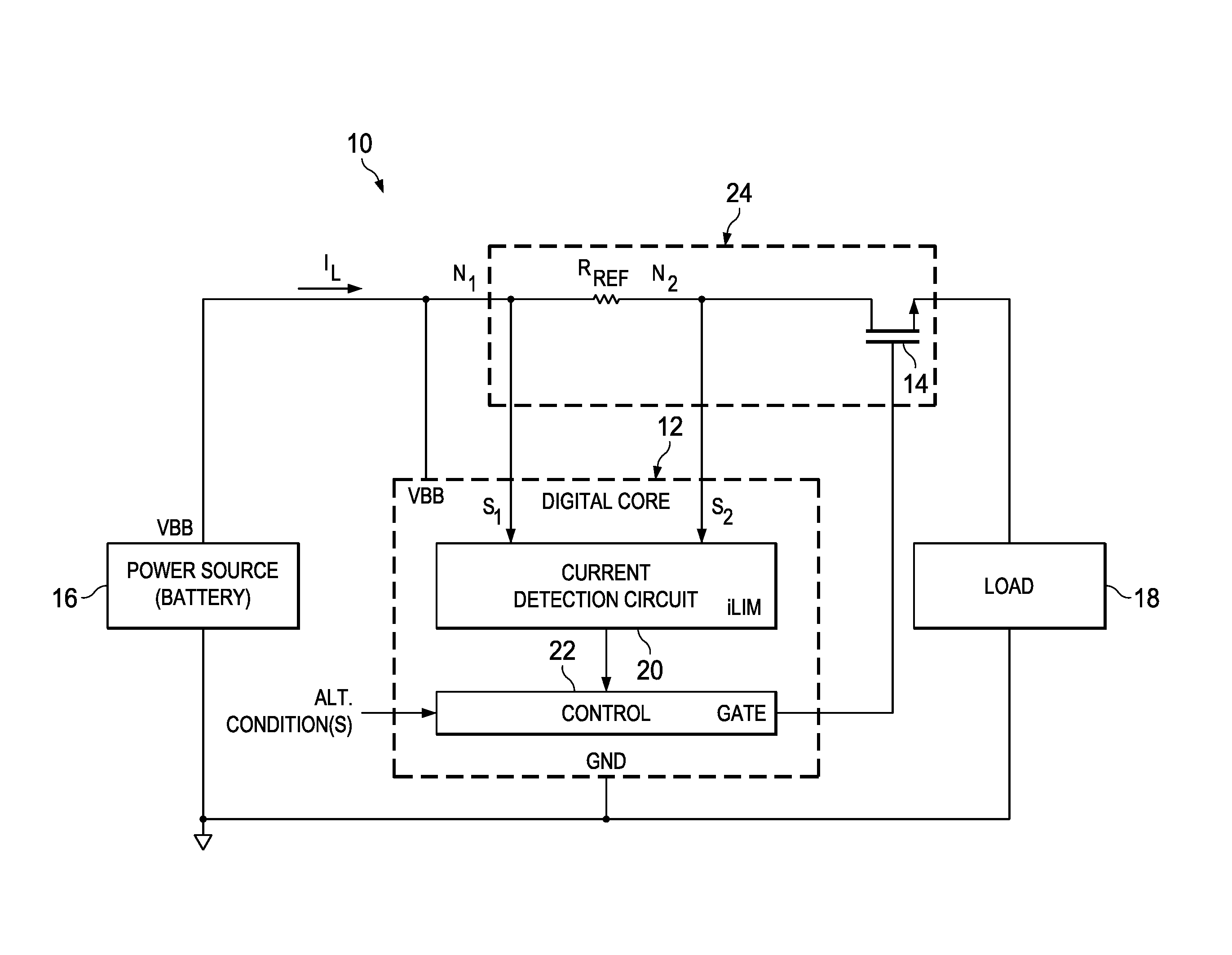
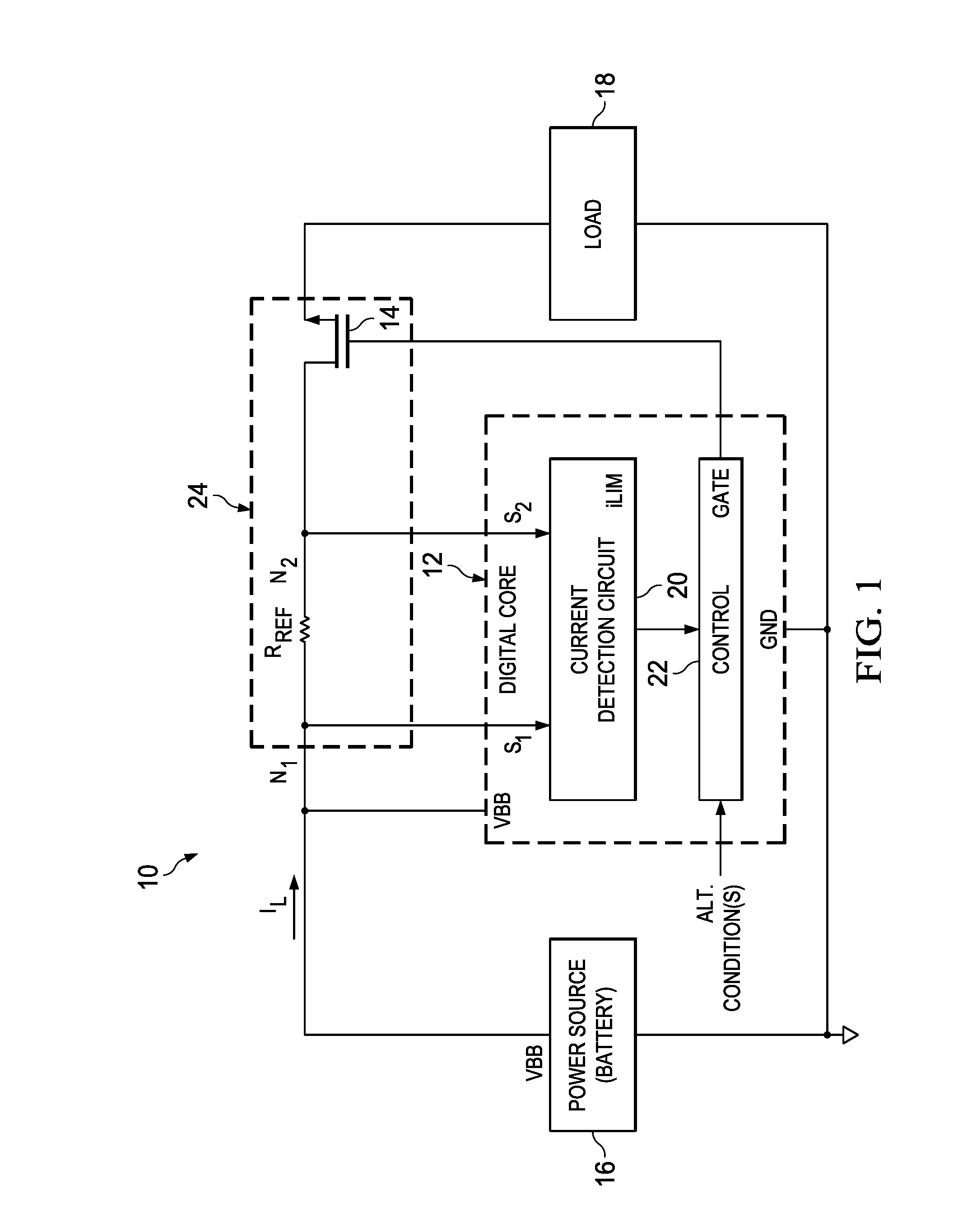
[0013]FIG. 1 illustrates a system 10 that in some general respects illustrates a controlled power delivery according to the prior art, but as is improved with aspects described in greater detail in this document. By way of the introduction, therefore, a general overview is presented in connection with FIG. 1, and preferred embodiment aspects are explained thereafter. System 10 includes a digital core 12, which may be constructed of various devices so as to achieve the functionality described below. For example, digital core 12 may be implemented as part of a processor (including appropriate programming) or as an integrated circuit module, akin in some respects to commercially available power controllers that are used in connection with thermal, current, or power detection of an associated power transistor 14, such as an n-channel MOSFET. One contemporary example for such a power controller is the TP52482 sold by Texas Instruments Incorporated, so the functionality of that device may...


PUM


Abstract

A circuit protective system. The system has: (i) an input for sensing an operational voltage responsive to a current flowing through a transistor; (ii) circuitry for applying a forced voltage at the input; (iii) voltage-to-current conversion circuitry for outputting a reference current in response to the forced voltage at the input; (iv) circuitry for providing a reference trim current in response to a trim indicator; and (v) comparison circuitry for outputting a limit signal in response to a comparison of the reference current and the reference trim current.

Description

CROSS-REFERENCES TO RELATED APPLICATIONS[0001]This application claims priority to, the benefit of the filing date of, and hereby incorporates herein by reference, U.S. Provisional Patent Application 62 / 202,411, entitled “MCM Ultra-High Current-Limit Test and Trim Procedure,” and filed Aug. 7, 2015.STATEMENT REGARDING FEDERALLY SPONSORED RESEARCH OR DEVELOPMENT[0002]Not Applicable.BACKGROUND OF THE INVENTION[0003]The preferred embodiments relate to electronic power driven systems, such as those driven with power field effect transistors (FETs).[0004]Certain electronically-driven power devices have high transient demands, such as at cold start-up, which tend toward requiring high current flow to meet the device (or customer) demands. For example, in automotive module applications, such as energizing an incandescent bulb coil at cold temperatures, very high peak in-rush current may be required to initially drive the coil, such as current demands in the range of approximately 90 A to 10...

Claims


Application Information

Patent Timeline
IPC IPC(8): G05F1/571G01R31/28
CPCG01R31/2827G05F1/571
Inventor RAHMAN, MD. ABIDURARAS, SUALPNGUYEN, TRI CAO
Owner TEXAS INSTR INC
Why Eureka
Try Eureka