Imaging system for processing a media
a technology of imaging system and media, applied in the direction of adaptive control, electric controller, instruments, etc., can solve the problems of degrading image quality, increasing the complexity and cost of the known imaging system, and increasing the difficulty in meeting the strict positioning tolerance, etc., to achieve precise stepping and high quality printing
- Summary
- Abstract
- Description
- Claims
- Application Information
AI Technical Summary
Benefits of technology
Problems solved by technology
Method used
Image
Examples
example 1
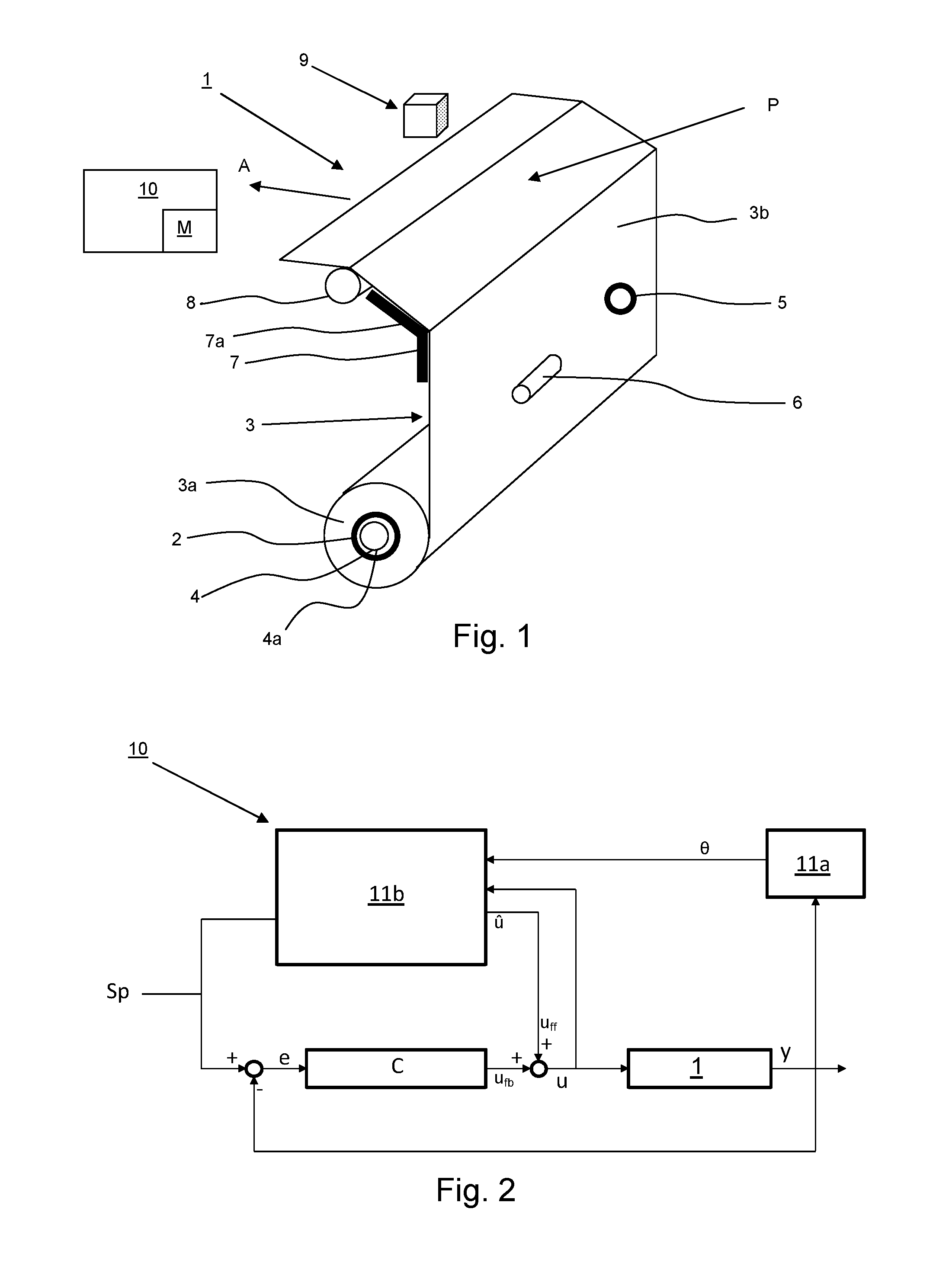
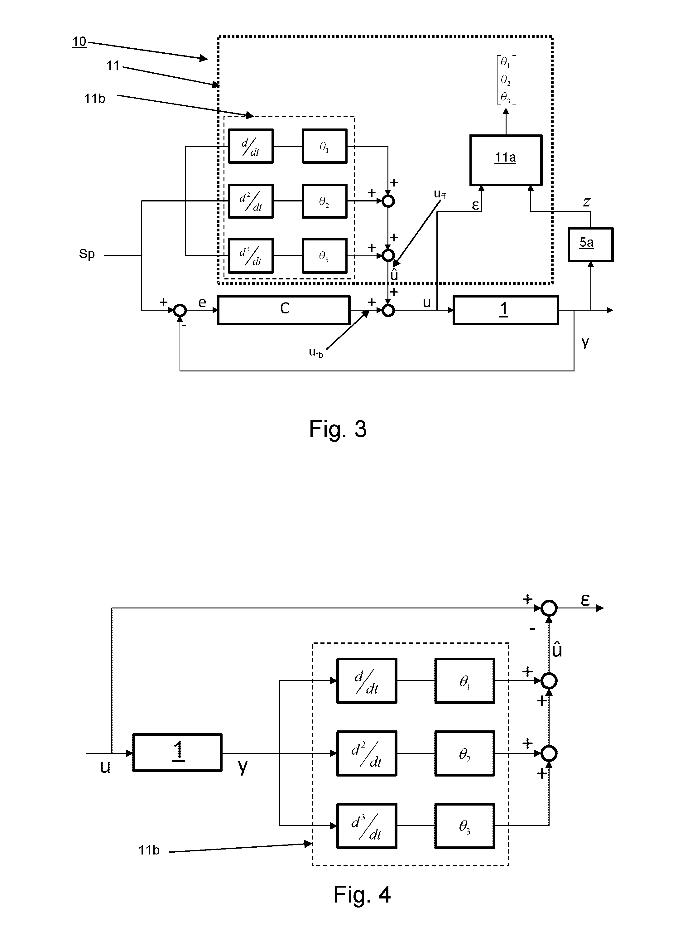
[0063]The controller assembly 10 in FIG. 3 further comprises a feedforward controller 11b, which may be either a hardware or software-based controller. The position setpoint Sp is applied as input for determining the feedforward component uff output by the feedforward controller 11b. From the position setpoint Sp, one or more time derivatives are derived as indicated by the blocks d / dt, d2 / dt2, d3 / dt3 in FIG. 3. Each block d / dt, d2 / dt2, d3 / dt3 corresponds to an order of the time derivative of the position setpoint Sp, i.e. d / dt is the first order time derivative of the position setpoint Sp, d2 / dt2 is the second order time derivative of the position setpoint Sp, etc. By converting the position setpoint Sp into a plurality of time derivative signals d / dt, d2 / dt2, d3 / dt3, the dynamics of the system 1 may be identified. The time derivatives d / dt, d2 / dt2, d3 / dt3 are combined with the status parameters θ1, θ2, θ3 to determine an actuation command estimate û. Preferably, a status parameter...
example 2
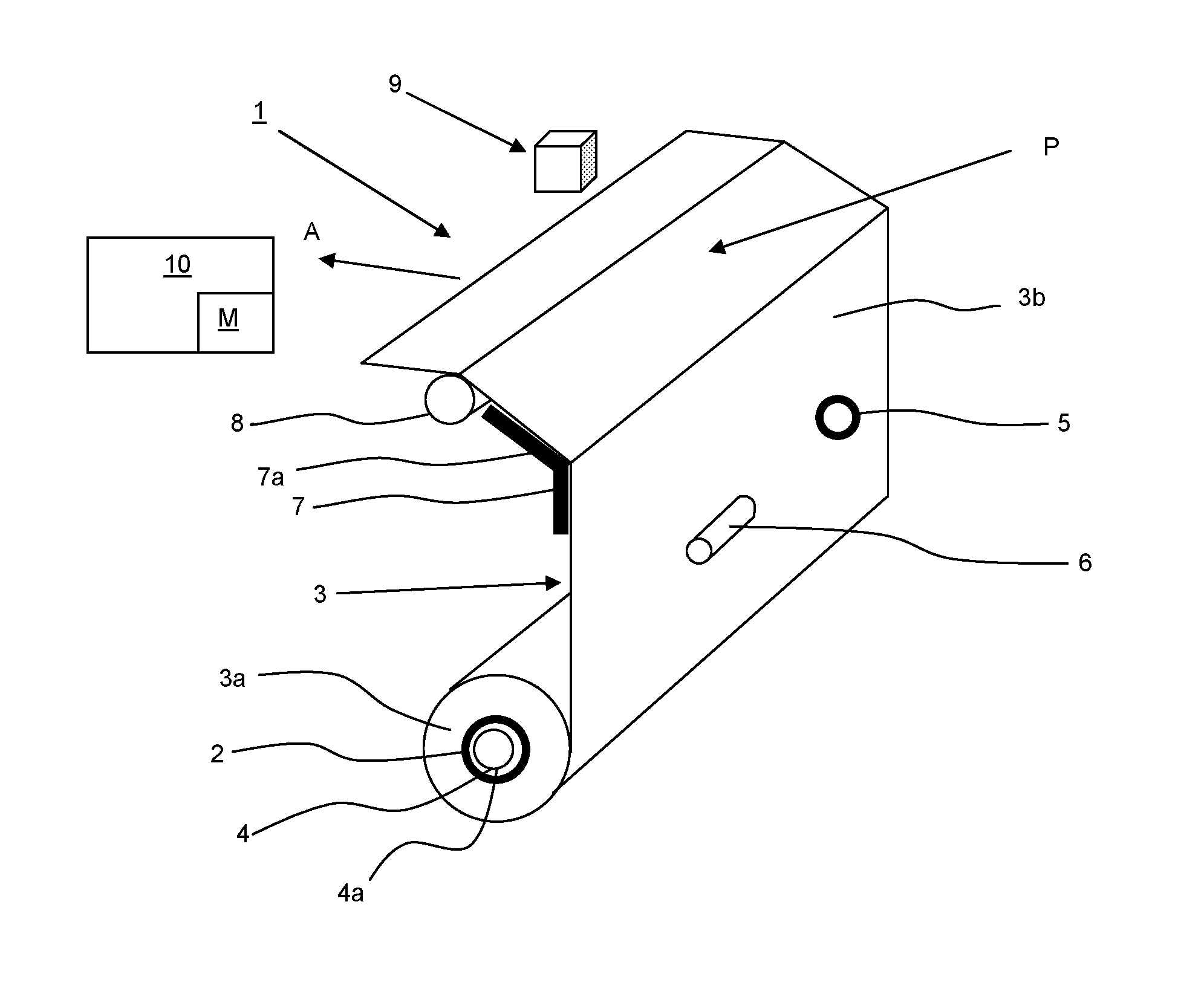
[0075]In FIG. 5, an imaging system 100 according to the present invention is illustrated as a block diagram. The imaging system 100 comprises a feedback controller assembly C′ and a feedforward controller with a feedforward algorithm 11b similar to those described with respect to FIGS. 1-3. The position signal y generated by the sensor device 5 is used as the basis for a feedback or a feedforward signal ufb, uff. FIG. 5 illustrates the different components of the position signal y, namely the angular signal y1 representing the angular position of the actuator 4, the tension signal y2 representing the tension in medium 3b, and the advancement signal y3 corresponding to the position of the medium 3. The position signal y3 may be generated by the encoder wheel 5, the tension signal y2 by means of the tension encoder 7a in the buffer 7, while the roll-motor encoder 4a may be applied for obtaining the advancement signal y1.
[0076]FIG. 5 shows that the observer 5a determines the medium rol...
PUM
 Abstract
Description
Claims
Application Information
 - R&D
- Intellectual Property
- Life Sciences
- Materials
- Tech Scout
- Unparalleled Data Quality
- Higher Quality Content
- 60% Fewer Hallucinations
Browse by: Latest US Patents, China's latest patents, Technical Efficacy Thesaurus, Application Domain, Technology Topic, Popular Technical Reports.
© 2025 PatSnap. All rights reserved.Legal|Privacy policy|Modern Slavery Act Transparency Statement|Sitemap|About US| Contact US: help@patsnap.com


