Load measuring transducer using induced voltage for reducing measuring errors and load measuring system using the same

a technology of measurement error reduction and transducer, applied in the field of load measurement sensor gauge, can solve the problems of adhesive distortion, non-uniform mechanical properties that cannot be easily predicted, and difficulty in implementing a load cell with a higher accuracy, and achieve the effect of more simplified structures and components and higher accuracy

Inactive Publication Date: 2011-12-27
PARK HEUNG JOON
View PDF37 Cites 1 Cited by
  • Summary
  • Abstract
  • Description
  • Claims
  • Application Information

AI Technical Summary

Benefits of technology

[0014]Accordingly, the present invention has been made in view of the above-described problems with conventional load measurement sensors and systems. An object of the present invention is to provide load measuring sensor gauges and a load measuring systems, which are capable of measuring loads with higher accuracy through more simplified structures and components.
[0015]Another object of the present invention is to conveniently avoid unnecessary error correction steps, and to increase measurement accuracy by eliminating errors caused by structural configurations that suffer from the aforementioned interference effects.

Problems solved by technology

It is very difficult to implement a load cell with accuracy higher than the above accuracy.
This is because there are problems in that typically a layer of adhesive is used to attach a strain gauge to its supporting structure, and the adhesive can distort.
Further, because the adhesive is made of polymer that has an inhomogeneous amorphous structure, the adhesive exhibits non-uniform mechanical properties that cannot be easily predicted.
Inherent features of typical strain gauges also adversely affect attaining higher accuracies.
Further, because it is difficult to achieve a uniform profile of the resistive material throughout the strain gauge, it is also difficult to obtain uniform deformation thereof that is proportional to a compressive or tensile strain of a structure.
However, since this load measuring transducer employs a very complicated mechanical mechanism, the load measuring transducer is difficult to manufacture and is very expensive.
In addition, there are electrical and spatial limitations on increases of electromagnetic force, serving as balancing forces for applied loads.
Further, since the complicated mechanical mechanism includes many thin hinges, there are problems in that it is not suitable for measurement of heavy loads and it is very vulnerable to external impacts.
Due to the above problems, such a load measuring transducer cannot easily be used in general-purpose commercial electronic scales or industrial electronic scales and only selectively used in special-purpose electronic scales.
However, the above prior art is problematic in that, as illustrated in FIG. 6, the short connecting electric wires, that are perpendicular to the longer wires of the electric wire patterns, influence the overall magnetic field of the device and cause measurement errors.

Method used


Image

  • Load measuring transducer using induced voltage for reducing measuring errors and load measuring system using the same
  • Load measuring transducer using induced voltage for reducing measuring errors and load measuring system using the same
  • Load measuring transducer using induced voltage for reducing measuring errors and load measuring system using the same

Examples


Embodiment Construction

[0039]Hereinafter, select embodiments of the present invention will be described in detail with reference to the accompanying drawings.

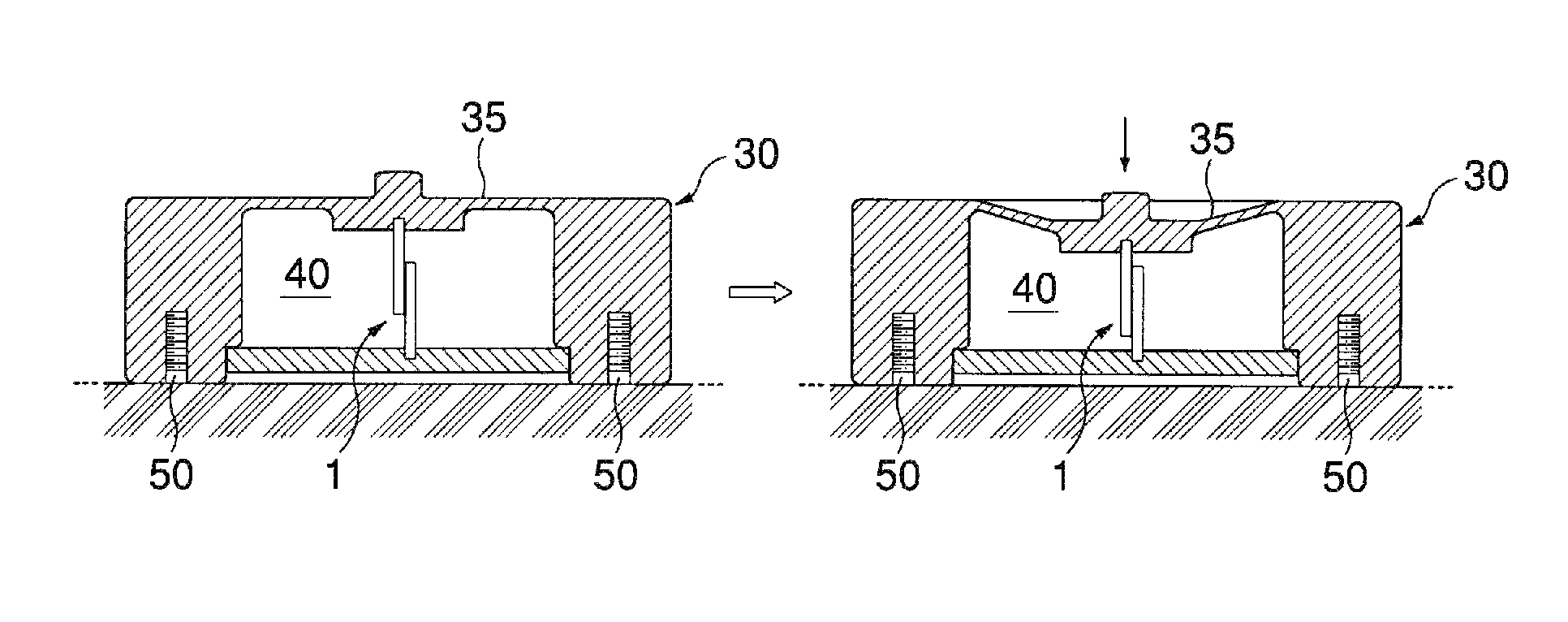
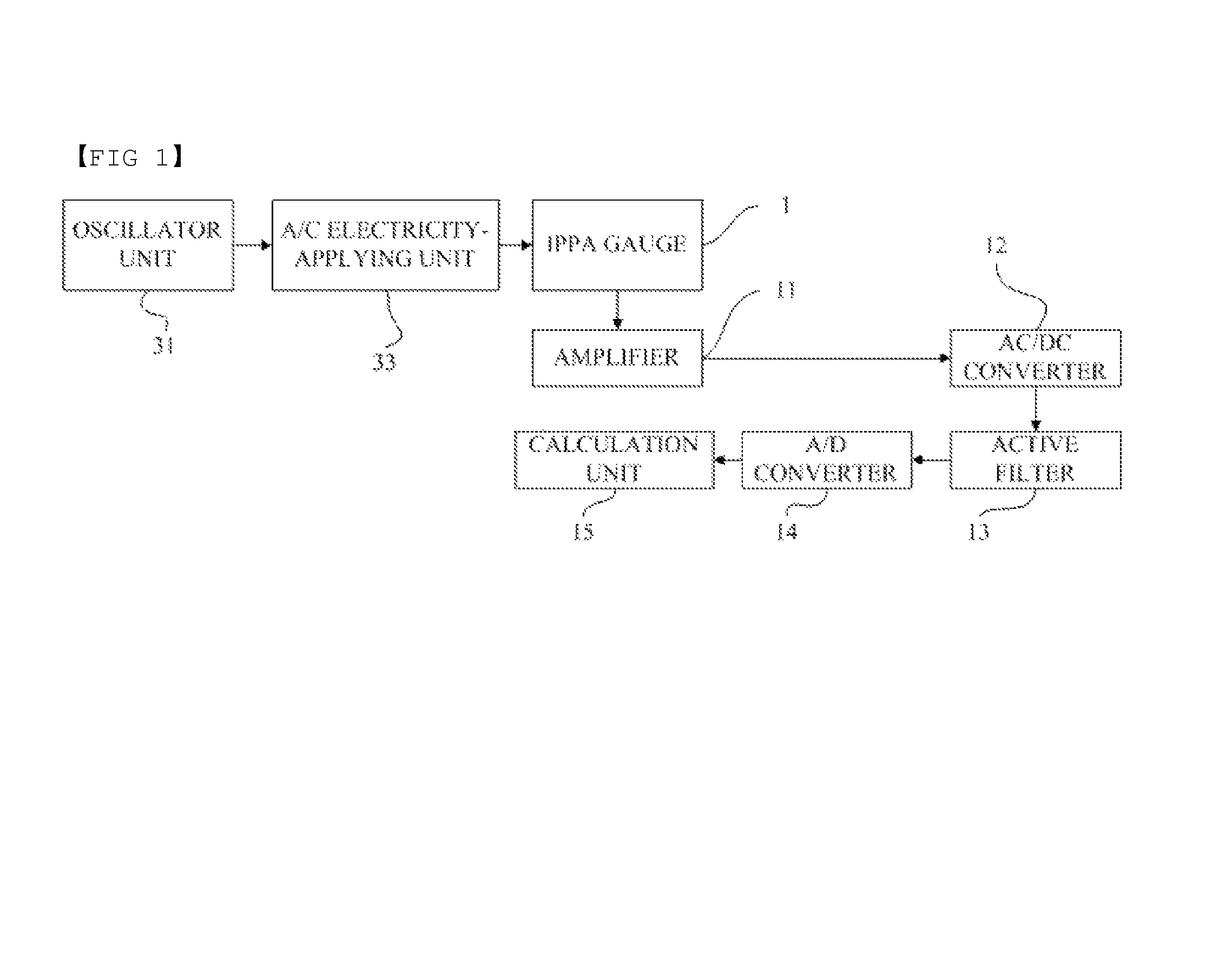
[0040]FIG. 1 shows an example of a system for measuring load, suitable for use with a load measuring sensor gauge according to the present invention. As shown in FIG. 1, the load measuring system of the present invention comprises an oscillator unit 31, an AC electricity-applying unit 33, an IPPA gauge 1, an amplifier 11, an AC / DC converter 12, an active filter 13, an A / D converter 14, a calculation unit 15 and can include a display (not shown). The term “IPPA gauge” used herein is an acronym for “Inductance Pattern Analogue Gauge”. In such gauges, AC is applied to one side (e.g. a stationary side) of the gauge. A voltage is induced in the other side of the gauge (e.g. the movable gauge), which varies with such movement. The induced voltage in the movable gauge is continuously measured, thereby measuring applied load in real time. Alternatively, the ...


PUM

PropertyMeasurementUnit
elastic deformationaaaaaaaaaa
induced voltageaaaaaaaaaa
electric fieldaaaaaaaaaa

Abstract

Load-measuring transducers utilizing induced-voltage measurement techniques are described. The wiring patterns of such transducers can be configured to reduce interference errors due to wiring patterns thereof.

Description

CROSS-REFERENCE TO RELATED APPLICATIONS[0001]This application claims the benefit of priority from Korean Patent Application No. 10-2009-0053594 filed on Jun. 16, 2009, which application is incorporated herein by reference in its entirety.BACKGROUND OF THE INVENTION[0002]1. Field of the Invention[0003]The present invention relates to load measuring sensor gauges for measuring loads, as well as to load measuring systems using such sensor gauges. More particularly, the present invention relates to sensor gauges and systems, wherein load is applied to an elastically deformable structure to produce an elastic deformation in the structure. The applied load is then measured using an induced-voltage sensor gauge configured to detect an induced voltage corresponding to the produced elastic deformation.[0004]2. Background of the Related Art[0005]Typically, general-purpose electronic scales, industrial electronic scales and the like utilize so-called “electric resistance type load cells”. Such...

Claims


Application Information

Patent Timeline
Patent Type & Authority Patents(United States)
IPC IPC(8): G01L1/22
CPCG01G3/12G01G7/02G01L1/14G01G3/14G01L1/16
Inventor PARK, HEUNG JOON
Owner PARK HEUNG JOON
Why Eureka
Try Eureka