Thermal sleeve with self-adjusting positioning member, assembly therewith and method protecting a temperature sensitive member therewith

Active Publication Date: 2017-02-09
FEDERAL MOGUL POWERTAIN LLC
View PDF3 Cites 2 Cited by
  • Summary
  • Abstract
  • Description
  • Claims
  • Application Information

AI Technical Summary

Benefits of technology

[0021]In accordance with another aspect of the invention, the method can further include providing the positioning member with a plurality of arcuate fingers and causing the plurality of arcuate fingers to compress radially outwardly along the plane toward the annular portion to grip the wiring harness and maintain the tubular member in shielding relation about the

Problems solved by technology

Due to the configuration of the aforementioned protective cylindrical sleeve and its harsh environment, it is typically difficult to assemble the sleeve about the sensor and elongate wire harness connected thereto in a manner which allows the sleeve to be reliably secured and maintained in a desired position, while at the same time being readily removable for servicing of the sensor.
Adhesives, tape and interference fits of an entirety of an inner surface of the cylindrical wall of the sleeve are used to effect attachment to the wire harness and to the sensor, but each of these mechanisms suffer various disadvantages.
Adhesive attachment of the sleeve about the sensor, while generally secure, at least initially, permanently attaches the sleeve to the sensor, and thus, complicates servicing the sensor at a future time, and in addition, the adhesives can breakdown over time, thereby causing the sleeve to become dislodged from its desired protective position about the sensor.
As a result, while in its initially bon

Method used


Image

  • Thermal sleeve with self-adjusting positioning member, assembly therewith and method protecting a temperature sensitive member therewith
  • Thermal sleeve with self-adjusting positioning member, assembly therewith and method protecting a temperature sensitive member therewith
  • Thermal sleeve with self-adjusting positioning member, assembly therewith and method protecting a temperature sensitive member therewith

Examples


Example

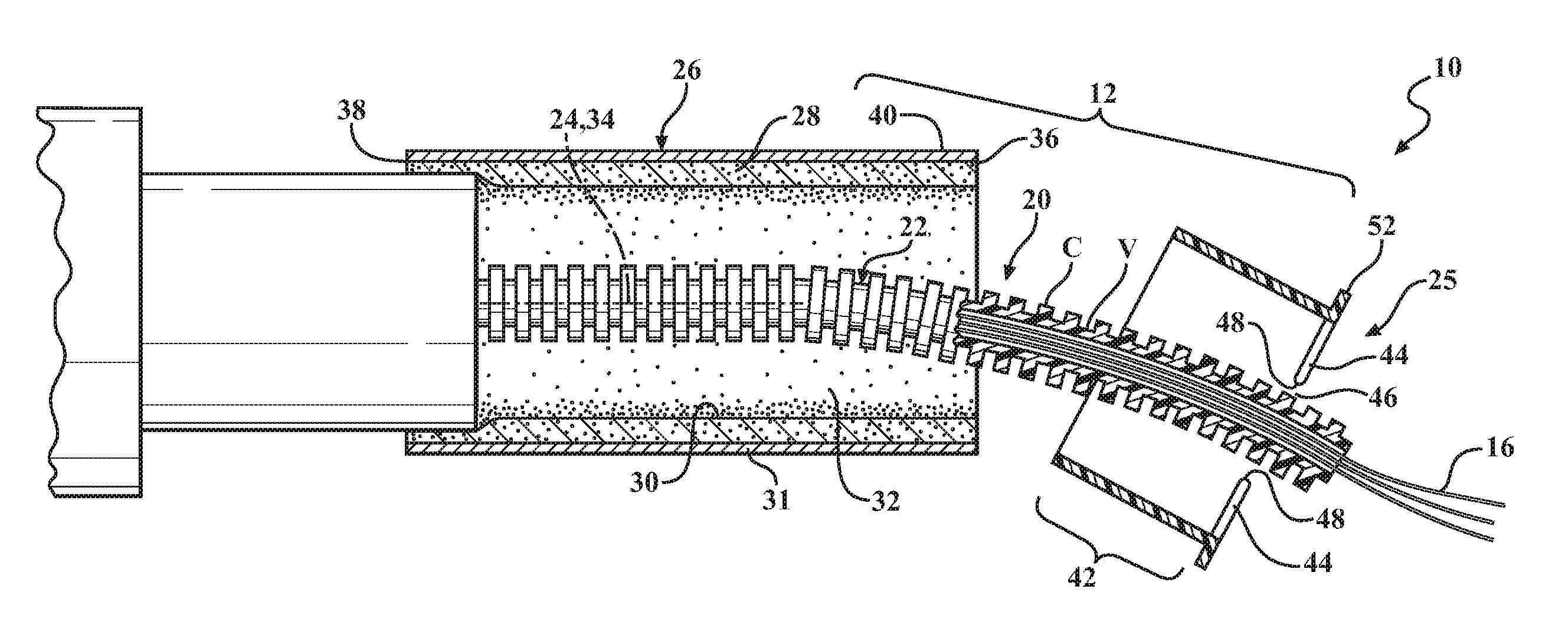
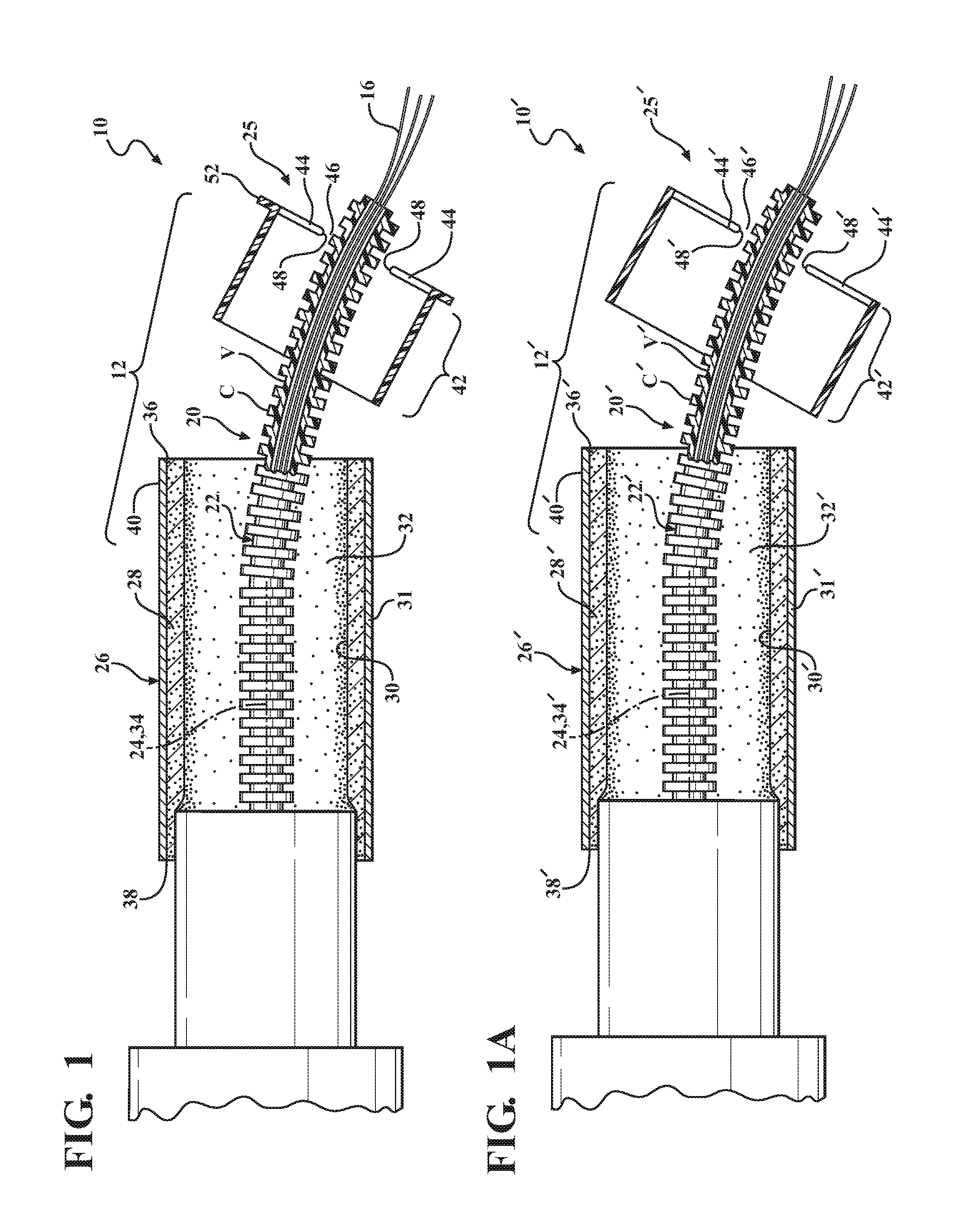
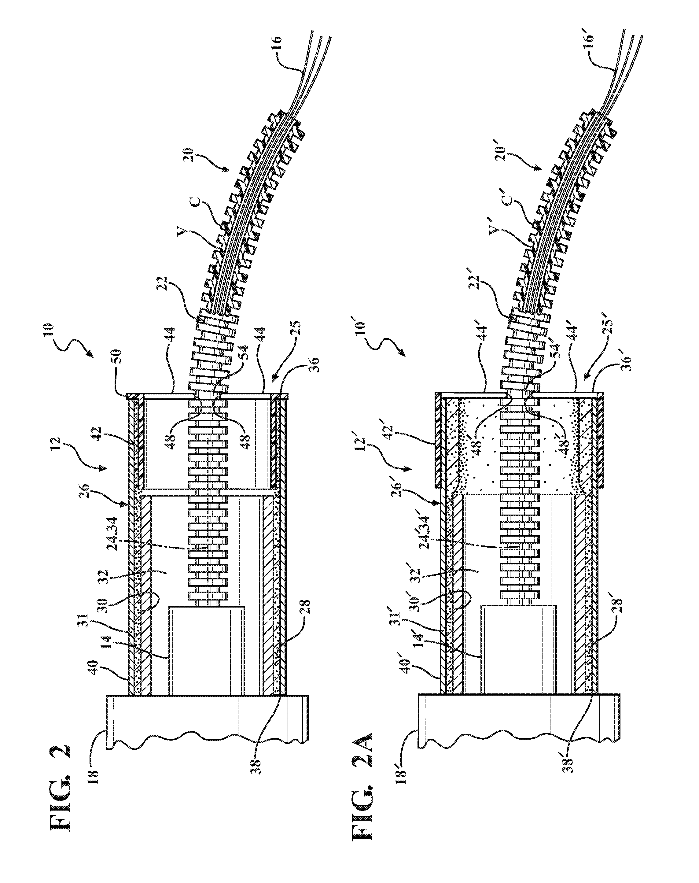
[0035]Referring in more detail to the drawings, FIGS. 1 and 2 show an assembly 10, including a thermal sleeve with a self-adjusting positioning member, referred to hereafter simply as sleeve assembly or simply sleeve 12, constructed in accordance with one aspect of the invention, for protecting a temperature sensitive member, such as an electrical member 14 contained, at least in part, therein, such as sensor, against the effects of extreme radiant heat, abrasion, contamination and vibration, wherein the sensor 14 is shown connected to an end of a wire harness 16 and to an engine component 18 of a vehicle (FIG. 2). The wire harness 16 can be provided as a bundle of exposed, insulated wires or as a bundle of insulated wires enclosed within an outer protective sleeve, also referred to as tube 20, such as a tube having a generally smooth or corrugated outer surface 22, by way of example and without limitation. The sleeve 12 is configured for slidable movement along a longitudinal axis ...


PUM


Abstract

A thermal sleeve and method for protecting a temperature sensitive electronic member against exposure to heat. The thermal sleeve includes a tubular wall with an inner surface bounding an inner cavity extending along a central longitudinal axis between open opposite ends and a reflective outer surface. The thermal sleeve includes a positioning member constructed of a separate piece of material from the tubular wall, with an annular portion attached to the tubular wall and at least one resilient finger extending radially inwardly from the annular portion. The at least one finger extends radially inwardly along a plane from the fixed end along an arcuate path to a free end configured for abutment with a wiring harness attached to the temperature sensitive electronic member. The free end of the finger is radially expandable along the plane toward the annular portion to automatically adjust to an outer envelop of said wiring harness.

Description

CROSS-REFERENCE TO RELATED APPLICATION[0001]This application claims the benefit of U.S. Provisional Application Ser. No. 62 / 200,763, filed Aug. 4, 2015, which is incorporated herein by reference in its entirety.BACKGROUND OF THE INVENTION[0002]1. Technical Field[0003]This invention relates generally to tubular sleeve assemblies that provide thermal protection to an electronic object contained therein, and more particularly to a tubular sleeve assembly including a positioning member to maintain the assembly in a selectively releasable, fixed position about the electronic object contained therein.[0004]2. Related Art[0005]Sensors used in automotive applications, such as oxygen sensors which provide data to control engine operation and performance, are often mounted within the engine compartment of a vehicle where they are subject to harsh environmental elements including intense radiant heat, sources of abrasion and vibration during vehicle operation. Due to the harsh environmental el...

Claims


Application Information

Patent Timeline
IPC IPC(8): H01B17/58H01B7/00H01B7/29
CPCH01B17/58H01B7/0045H01B7/292B60R16/0215F01N2560/025H02G3/088
Inventor DEPOMPEO, NICHOLAS
Owner FEDERAL MOGUL POWERTAIN LLC
Why Eureka
Try Eureka