
Water treatment apparatus and method

a technology of water treatment apparatus and water treatment method, which is applied in the direction of treatment water nature, separation process, polycrystalline material growth, etc., can solve the problems of environmental and economic damage, environmental damage, and the initial cost of the introduction of the equipment for this method is extremely high, so as to achieve the effect of not affecting the ecology and environmental damage, avoiding environmental damage, and avoiding environmental damag

Inactive Publication Date: 2008-04-22
SANYO ELECTRIC CO LTD +1
View PDF10 Cites 0 Cited by
  • Summary
  • Abstract
  • Description
  • Claims
  • Application Information

AI Technical Summary

Benefits of technology

[0012]The present invention is directed to solve the environmental problems set forth above related to rivers and oceans. An object of the present invention is to provide an apparatus and method of treating, economically and with favorable efficiency in energy and time, waste water discharged from medical facilities such as hospitals to a level so as not to influence the ecology. More specifically, an object of the present invention is to provide an apparatus and method of treating a pharmaceutical drug included in waste water by decomposing or altering partially the structure of the pharmaceutical drug through electrolysis to render inactive the pharmaceutical drug, such that it will not affect the ecology and environment of rivers and the like.

Problems solved by technology

If the waste is not treated to a level of eliminating or reducing the pharmacological activity before being discharged into the river, there is a possibility of the ecology and environment being adversely affected potentially.
The initial expense to introduce the equipment for this method as well as the running cost thereof are extremely high.
Furthermore, considerable energy is required for incineration and evaporation, and the energy efficiency is poor.
There is also a problem that the discharged amount of carbon dioxide is great.
The efficiency from the standpoint of time is also poor since the waste fluid must be transported from the medical facility to the incineration facility.
Furthermore, the cost for transportation will be incurred.

Method used


Image

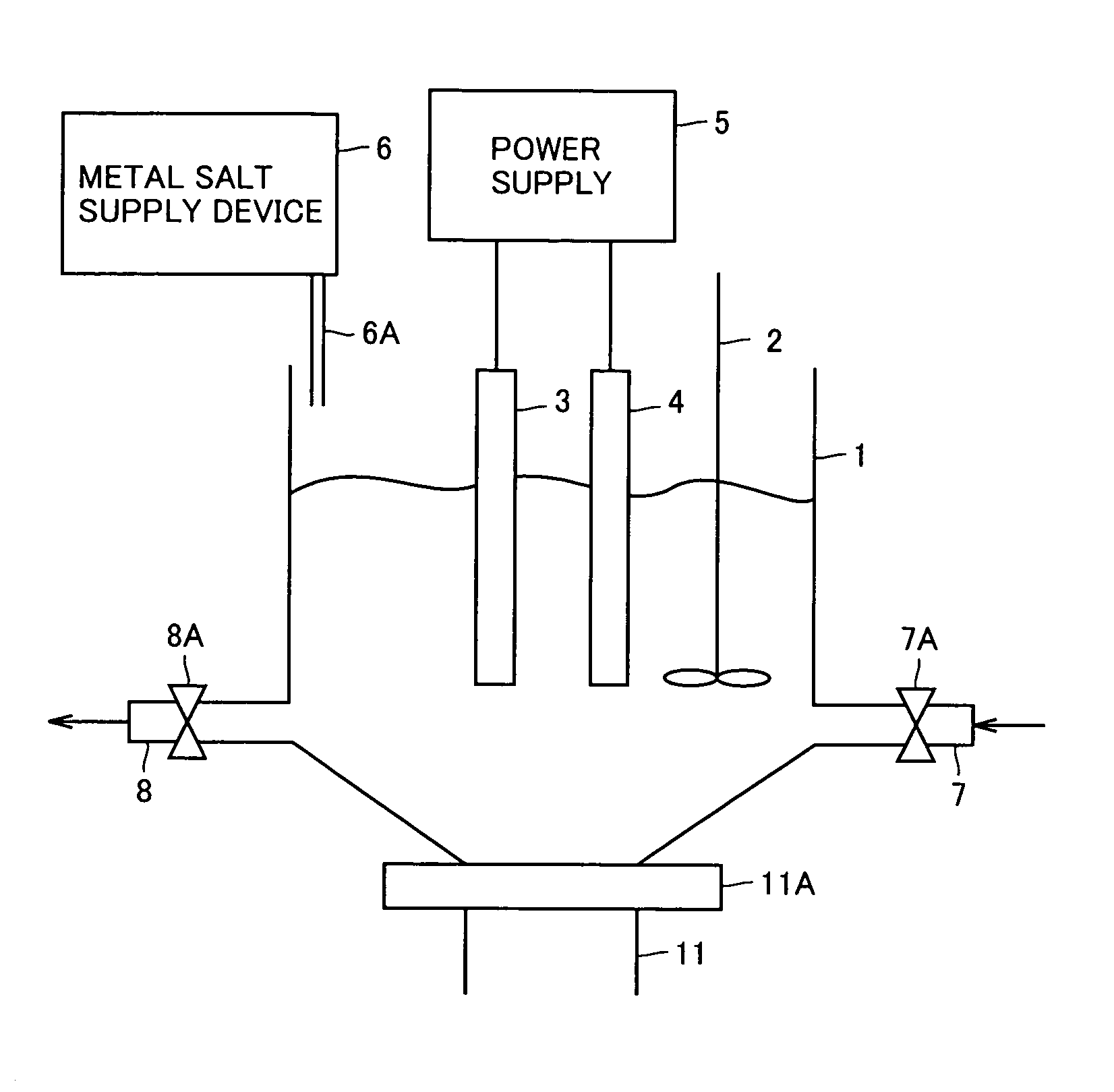
  • Water treatment apparatus and method
  • Water treatment apparatus and method
  • Water treatment apparatus and method

Examples


example 1

Inactivation of Sterilant by Electrolysis

1. Electrolyzer

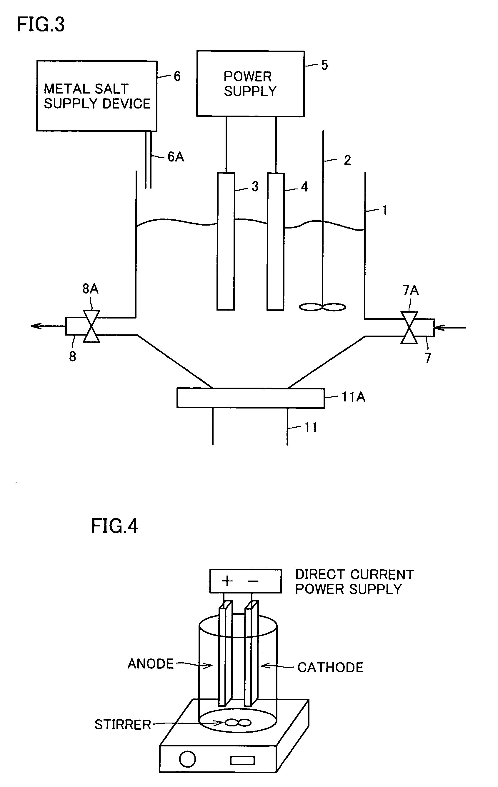
[0177]The apparatus of FIG. 4 was employed to confirm that the activity of the sterilant, antibiotic, and anticancer drug set forth above has been eliminated or reduced by electrolysis in the present example. FIG. 4 schematically shows an electrolytic cell employed in electrolysis. A pair of Pt electrodes is inserted in a 200 ml-container. Each electrode is connected to a direct current power supply. One and the other of the electrodes are established as an anode and a cathode, respectively. The distance between the anode and cathode is 10 mm. Each electrode has the size of 3.5×5 cm. The fluid in the container can be mixed by the rotation of a stirrer upon a magnetic field being applied by a magnetic device provided at the bottom of the container.

2. Electrolysis

[0178]A buffer agent of 0.3 ml was mixed into 2 mass % of 10 ml-Sterihide (R) (available from MARUISHI Pharmaceutical Co. Ltd.). Then, pure water was further added to se...

example 2

Inactivation of Antibiotic by Electrolysis

1. Electrolyzer

[0203]An electrolyzer identical to that of Example 1 was employed in the present Example 2.

2. Electrolysis

[0204]One ample of amikacin sulfate (obtained from BANYU PHARMACEUTICAL CO. LTD., 200 mg titer, 2 ml) was mixed into 200 ml of 0.1% of NaCl solution. This mixture was introduced into the container of FIG. 4. Direct current was applied for 6 hours to establish the current density of 4 A / dm2. Samples of the electrolyte were taken 0, 1, 2, 3, 5, and 6 hours from initiation of electrolysis.

[0205]Into the electrolyte samples taken at respective hours from initiation of electrolysis was added 250 μl of 1% sodium thiosulfate solution as a neutralizer to prepare samples with the residual chlorine and combined chlorine set to 0.

3. Analysis of Electrolyzed Solution

[0206]The samples of amikacin sulfate after electrolysis was evaluated by ion chromatograph (DIONEX X-120), total nitrogen analyzer (Mitsubishi Chemical Corporation TN-30)...

example 3

Inactivation of Anticancer Drug of Antitumor Antibiotics by Electrolysis

1. Electrolyzer

[0241]The electrolyzer employed in Example 3 was substantially similar to that employed in Example 1, provided that Pt-Ir material was employed as the electrode having the size of 35×8 mm. The electrodes were set apart 5 mm from each other.

2. Electrolysis

[0242]20 mg of NaCl was added into 1 vial of epirubicin hydrochloride (using “Farmorubicin RTU injection” of KYOWA HAKKO KOGYO CO., LTD., including 10 mg titer of epirubicin hydrochloride in 1 vial (5 ml)). The mixture was introduced into the container of FIG. 4. Direct current was applied for 6 hours so that current density of 4 mA / dm2 was established. Samples were taken 0, 2, 4, and 6 hours from initiation of electrolysis.

[0243]Into the electrolyte samples corresponding to respective electrolyzing hours was added 25 μl of sodium thiosulfate solution as a neutralizer to prepare samples with the residual chlorine and combined chlorine set to zero....


PUM

PropertyMeasurementUnit
distanceaaaaaaaaaa
sizeaaaaaaaaaa
current densityaaaaaaaaaa

Abstract

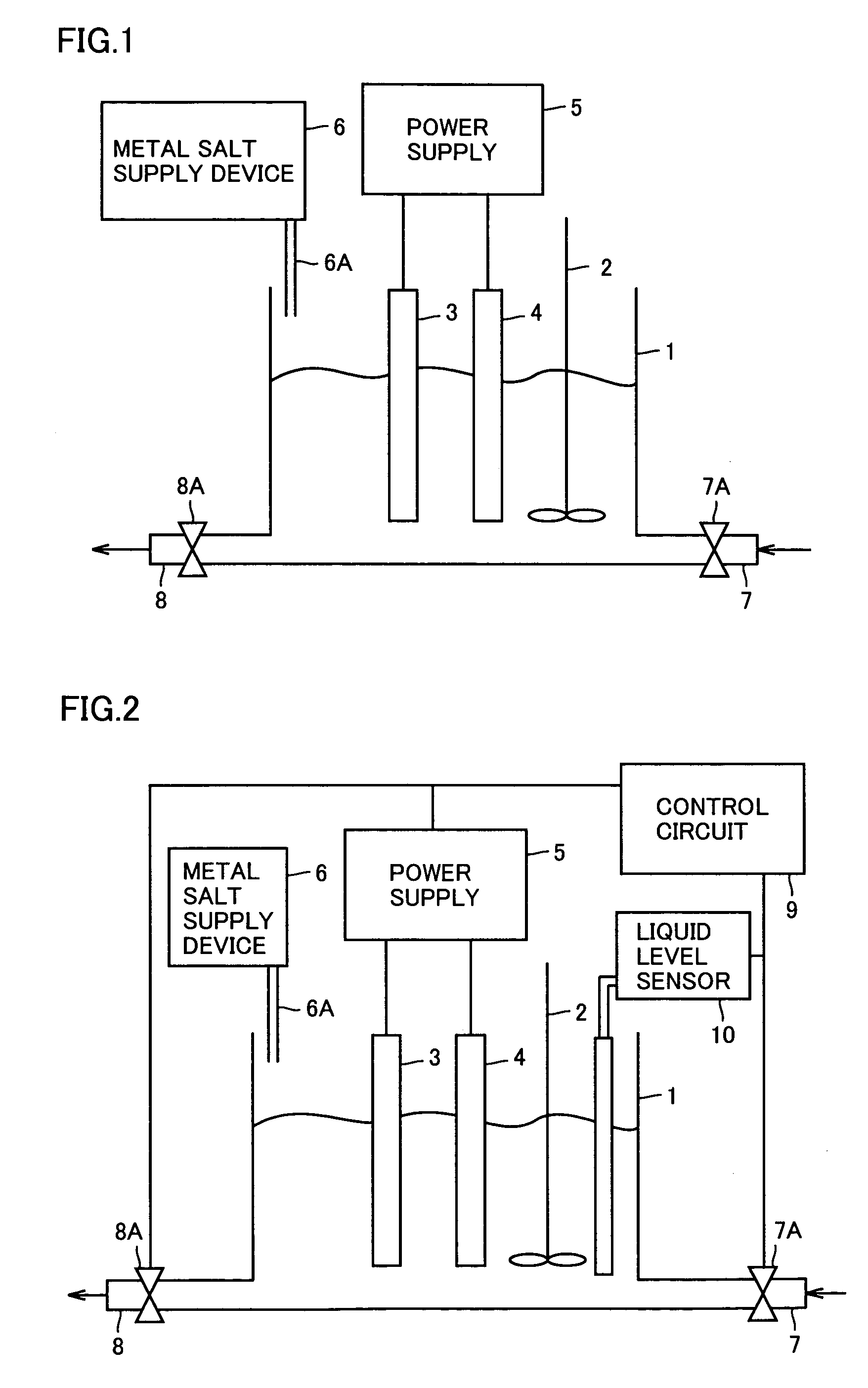
A water treatment apparatus includes a storage unit storing water to be treated including a pharmaceutical drug, an apply unit applying the water to be treated to the storage unit, an addition unit adding into the water to be treated metal salt generating halide ions when dissolved in the water to be treated, and an energizing unit applying a current to a pair of electrodes immersed in the water to be treated in the storage unit. The pharmacological activity of the pharmaceutical drug is eliminated or reduced by decomposing or altering at least a portion of the chemical structure of the pharmaceutical drug included in the water to be treated through electrolysis.

Description

BACKGROUND OF THE INVENTION[0001]1. Field of the Invention[0002]The present invention relates to a method of treating waste water discharged from medical facilities. More specifically, the present invention relates to an apparatus and method of treating pharmaceutical drugs included in waste water by means of electrolysis to the extent that the pharmacological activity and toxicity thereof are eliminated or reduced to an acceptable level.[0003]2. Description of the Background Art[0004]Nature including the river and ocean is affected in one way or another by the activities of humans. Usage of water supplied from rivers and oceans as well as sewerage releasing used water back to the rivers are critical factors in the environment. As to the issue of sewerage, the used water output from households, companies, plants and the like, i.e. waste water, should be restored as close as possible to the former state before being dispatched back to the rivers and oceans for environmental reasons. ...

Claims


Application Information

Patent Timeline
Patent Type & Authority Patents(United States)
IPC IPC(8): C02F1/461C02F1/46C02F1/467
CPCC02F1/4672C02F1/46109C02F2001/46133C02F2101/30C02F2101/305C02F2101/327C02F2101/38C02F2103/343C02F2201/4618C02F2209/42
Inventor HIROSE, JUNKONDO, FUMITAKEHIRO, NAOKISANO, KOUICHINAKANO, TAKASHITAKENAKA, HIROSHIANDO, YOKOKOBAYASHI, TOYOHIDE
Owner SANYO ELECTRIC CO LTD
Learn More