Superconducting device and method for inducing low relaxation rate in superconducting material

Inactive Publication Date: 2017-02-09
UNITED STATES OF AMERICA THE AS REPRESENTED BY THE SEC OF THE ARMY +1
View PDF6 Cites 2 Cited by
  • Summary
  • Abstract
  • Description
  • Claims
  • Application Information

AI Technical Summary

Benefits of technology

The patent is about a way to easily create electric current in superconducting materials. It can be used to test new materials or make sure they are resistant to relaxation, which is a form of electromagnetic interference.

Problems solved by technology

Initial materials found to possess this property included materials such as Nb3Sn with a critical temperature of 18.3° K. and NbT with a critical temperature of 10° K. An issue with these early recognized materials is that reaching the critical temperature is difficult to achieve and commonly requires the use of liquid helium.
Although these first generation materials addressed the problem of expensive cryogenics, production of these materials often relies on the use of very expensive silver making wide scale adoption of these materials economically difficult.
The use of these materials, however, has been hampered by the unavailability of satisfactory joining techniques and production issues.
Some advances have been made in the formation of such joints, but their usefulness in large format applications has yet to be proven.
Further, the use of such materials in large scale operations requires excellent quality control, and simple and effective methods of such quality control are presently lacking.

Method used


Image

  • Superconducting device and method for inducing low relaxation rate in superconducting material
  • Superconducting device and method for inducing low relaxation rate in superconducting material
  • Superconducting device and method for inducing low relaxation rate in superconducting material

Examples


example 1

[0039]A resistive solenoid is formed of a copper wire of gauge 25 by winding around a brass solenoid support tube with a diameter of 12.6 mm a total of 300 times. The termini of the wire are connected to a direct current power source to generate a current though the solenoid.

[0040]A coil former made of brass and having an inner diameter of 18.8 mm and outer diameter of 22.1 mm suitable to fit over the resistive solenoid is placed over the resistive solenoid so as to entirely encompass the resistive solenoid.

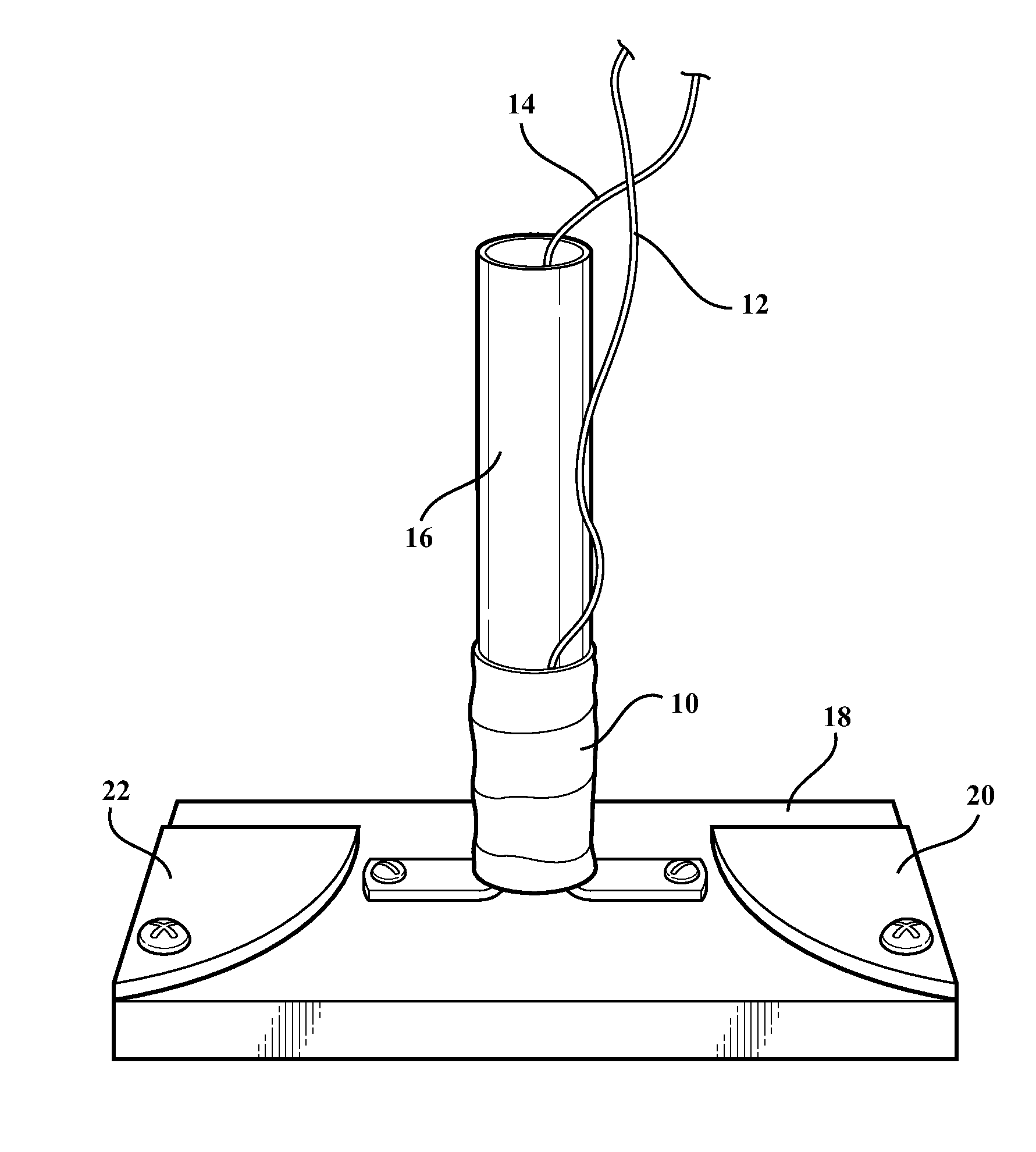
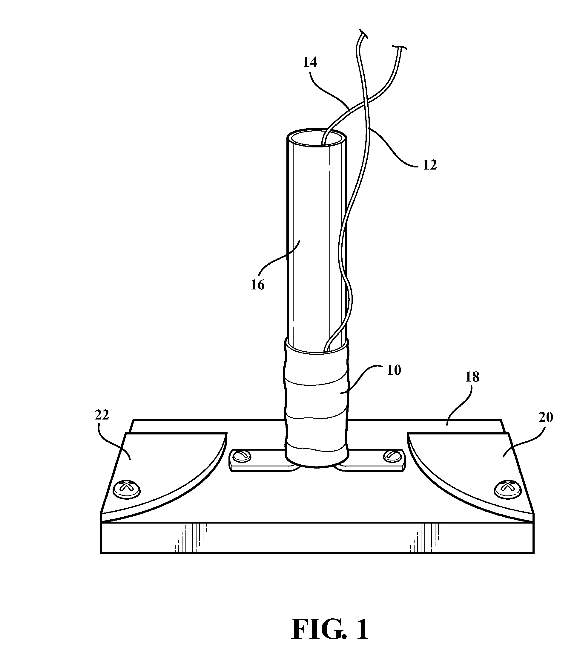
[0041]A superconducting material purchased from SuperPower Inc. (SuperPower coated conductor product batch number M3-1060-3 SF12050-AP, with critical current of 309 A) was cut into samples of 110 mm in length. A 1 mm wide slit was milled in each of them resulting in the loops shown in FIG. 2. They were stacked together making a “coil” with 2 to 6 loops per coil and the main diameter of 22.6 mm. To preserve the quality of the superconducting material, the coils were encapsulated i...

example 2

[0043]The device of Example 1 is immersed in liquid nitrogen to cool the superconducting material to a temperature below its critical temperature. During this time, a DC electric current is passed through the resistive solenoid at 3 A. When the critical temperature of the system of 77° K. is reached, the current is terminated which inducted the superconducting current through the superconducting material as observed by a Gaussmeter inserted into the inner diameter of the solenoid support tube. The magnetic field is directly proportional to the circulating in the loop superconducting current, so that the change in measured magnetic field directly reflects the change in the superconducting current. The changes in the superconducting current over time are depicted as the control run in FIG. 4 illustrating the expected rate of relaxation for this superconducting material.

[0044]To reduce the rate of relaxation, a modified current sweep reversal is used to generate an electric current thr...


PUM

PropertyMeasurementUnit
Diameteraaaaaaaaaa
Diameteraaaaaaaaaa
Currentaaaaaaaaaa

Abstract

Provided are devices for inducing a current in a closed loop superconducting material including a magnetic field source housed within a coil former substantially coaxial with the magnetic field source, and a base optionally in physical contact with a support tube. A closed loop superconducting material is held in a loop position by the coil former and the base such that current passing through the magnetic field source will produce a current in the superconducting material by induction. By a process of modified current sweep reversal, the rate of relaxation may be reduced in the superconducting material relative to the absence of a reversal.

Description

GOVERNMENT INTEREST[0001]The invention described herein may be manufactured, used, and licensed by or for the United States Government.FIELD[0002]The present invention relates generally to the field of superconducting materials. More specifically, a device is provided for inducing a current in a closed loop of superconducting material. Methods of reducing the current relaxation rate are provided as well.BACKGROUND[0003]Superconducting materials have the ability to conduct electrical current with zero resistance when the materials are cooled below the material's transition temperature. Initial materials found to possess this property included materials such as Nb3Sn with a critical temperature of 18.3° K. and NbT with a critical temperature of 10° K. An issue with these early recognized materials is that reaching the critical temperature is difficult to achieve and commonly requires the use of liquid helium.[0004]The development of high temperature superconducting (HTS) materials add...

Claims


Application Information

Patent Timeline
IPC IPC(8): H01F7/20H01F6/06C22C29/12H01F7/06
CPCH01F7/20C22C29/12H01F6/06H01F7/064H01F6/006
Inventor LEVIN, GEORGE A.BARNES, PAUL N.RONG, CHARLES C.
Owner UNITED STATES OF AMERICA THE AS REPRESENTED BY THE SEC OF THE ARMY
Why Eureka
Try Eureka