Device including an electric machine with a lightweight design

a technology of electric machines and devices, applied in the field of devices, can solve the problems of considerable shear and bending loads in the connecting structure, and achieve the effect of increasing the stability of the second strut and greater stability

Active Publication Date: 2017-02-09
ROLLS ROYCE DEUT LTD & CO KG
View PDF6 Cites 10 Cited by
  • Summary
  • Abstract
  • Description
  • Claims
  • Application Information

AI Technical Summary

Benefits of technology

[0013]Via this refinement, forces that tend to effect twisting of the support ring are kept as low as possible.
[0014]In one embodiment, the second struts have a second strut width as viewed about the axis of rotation and have a strut height as viewed in the direction of the axis of rotation. The strut height is greater than the second strut width. This refinement leads to increased stability of the second struts in relation to a bending force that acts in the directio...

Problems solved by technology

Considerable shear and bending l...

Method used


Image

  • Device including an electric machine with a lightweight design
  • Device including an electric machine with a lightweight design
  • Device including an electric machine with a lightweight design

Examples


Embodiment Construction

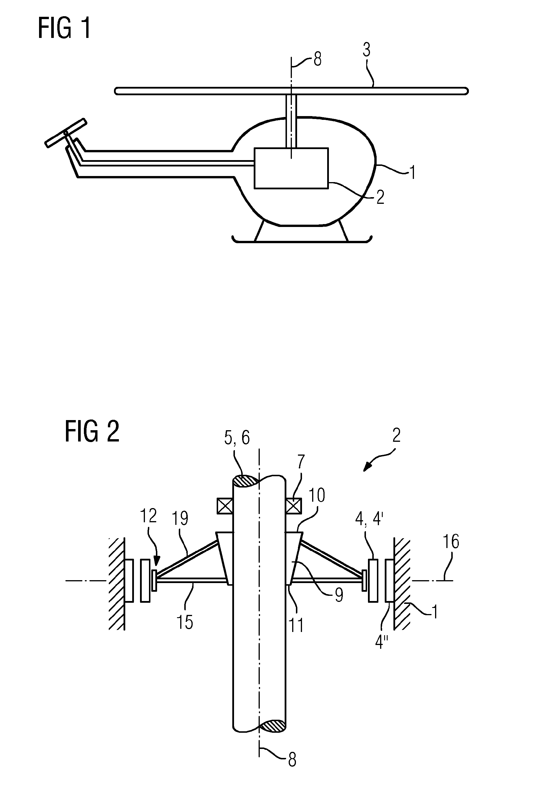
[0030]As shown in FIG. 1, a device includes a main body 1. In FIG. 1, the device is an aircraft (e.g., a helicopter). The main body 1 may, for example, be the fuselage of the aircraft. The illustration of FIG. 1 is, however, merely an example. In principle, the main body 1 may be of any desired design.

[0031]In the main body 1, an electric machine 2 is arranged. The electric machine 2 drives an assembly 3 of the device. For example, the electric machine 2 may be in the form of a main drive of the device.

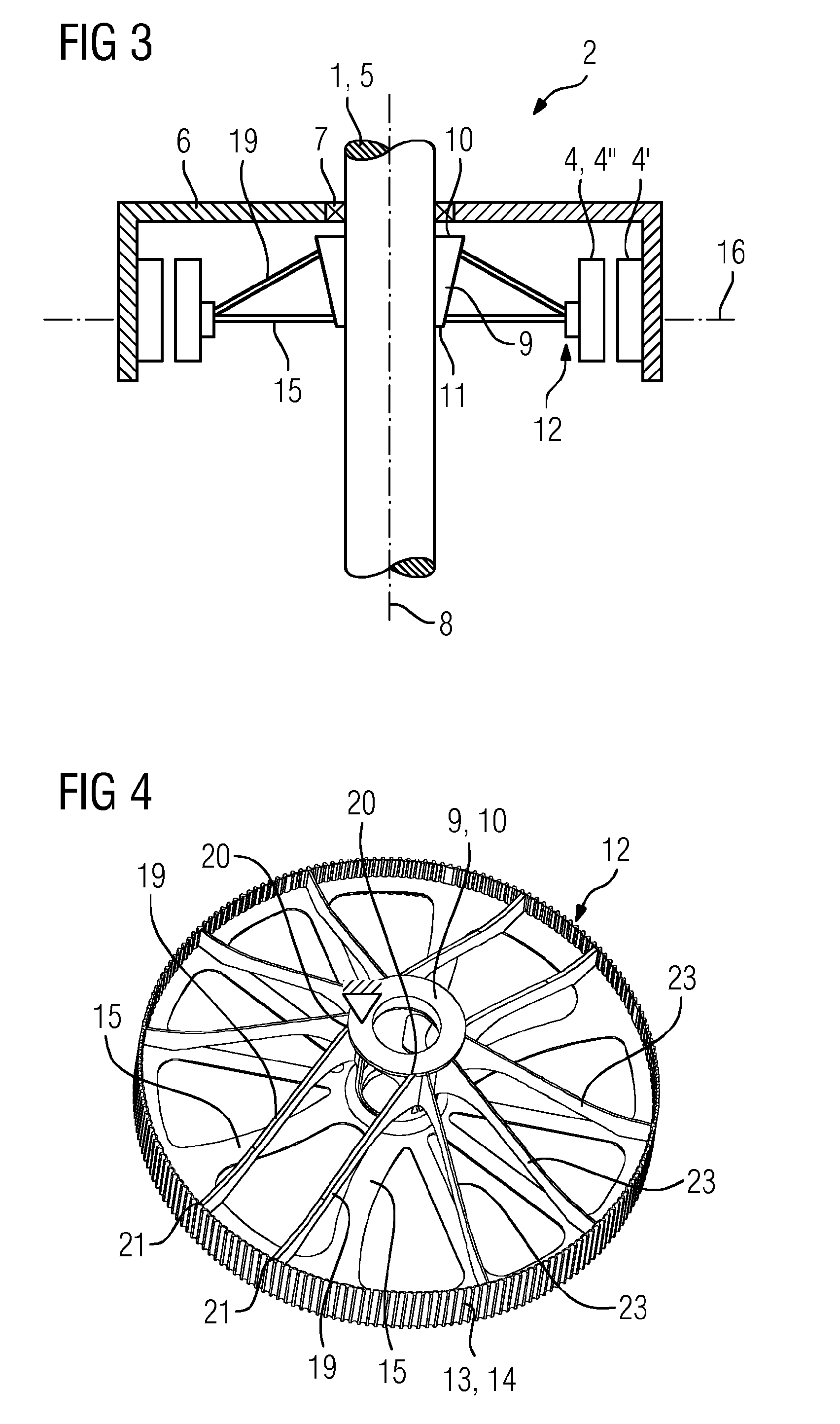
[0032]In FIG. 2, the electric machine 2 is in the form of an internal-rotor machine. In this case, a first active part 4 of the electric machine 2 is in the form of the rotor 4′ of the electric machine. A second active part of the electric machine 2 is, for example, in the form of the stator pack 4″ of the electric machine. A support body 5 of the device is in the form of a rotor shaft 6 of the electric machine 2.

[0033]In FIG. 3, the electric machine 2 is in the form of an external-ro...


PUM


Abstract

An active part (4) of an electric machine (2) is connected to a supporting body (5) via a connecting structure and is fixed relative to the supporting body (5). A rotor (4′) of the electric machine interacts electromagnetically with a stator core (4″) and is mounted rotatably relative to the stator core (4″) so that the rotor (4′) is rotatable about an axis of rotation (8). The connecting structure comprises at least one hub (9), a supporting ring (12) and first and second struts (15, 19). The hub (9) surrounds the axis of rotation (8) and extends in the axial direction from an upper hub end (10) to a lower hub end (11). The hub (9) adjoins, with the upper hub end (10), the supporting body (5) and is fastened there to the supporting body (5). The supporting ring (12), on the outer side (13) thereof, adjoins the active part (4) and is connected to the active part (4). The first struts (15) extend in a radial plane (16) radially outwards from the lower hub end (11) to the supporting ring (12). The first struts (15) merge with the hub (9) in a respective radially inner transition region (17) and with the supporting ring (12) in a respective radially outer transition region (18). The second struts (19) extend from the upper hub end (10) to the supporting ring (12). In relation to the radial plane (16), the radially inner transition region (17) and the radially outer transition region (18) of a respective first strut (15) each form an angle (a) with the axis of rotation (8).

Description

[0001]This application is the National Stage of International Application No. PCT / EP2014 / 074896, filed Nov. 18, 2014, which claims the benefit of German Patent Application No. EP 13194465.4, filed Nov. 26, 2013. The entire contents of these documents are hereby incorporated herein by referenceBACKGROUND[0002]The present embodiments relate to a device having a support body, where an active part of an electric machine is connected to the support body and is fixed relative to the support body via a connecting structure.[0003]In the context of mobile applications, the power-to-weight ratio of the electric machine plays a major role. For example, it is sought to reduce the weight of the electric machine as far as possible. Weight savings are sought both in the case of the active parts (e.g., electromagnetically active components; magnets and coils and laminations or lamination pack; rotor and stator pack) and in the case of the other components, the passive parts.[0004]If the direct moun...

Claims


Application Information

Patent Timeline
IPC IPC(8): H02K7/14B64C27/14H02K1/22H02K5/00H02K7/08H02K1/12
CPCH02K7/14H02K7/08B64C27/14H02K1/22H02K5/00H02K1/12H02K1/30H02K9/06H02K2213/03
Inventor BALLAUF, CHRISTIAN
Owner ROLLS ROYCE DEUT LTD & CO KG
Why Eureka
Try Eureka