Floating solar panel array with one-axis tracking system

a solar panel and tracking system technology, applied in the field of photovoltaic systems, can solve the problems of negative environmental impact and huge land area

Active Publication Date: 2017-02-09
4CSOLAR
View PDF5 Cites 29 Cited by
  • Summary
  • Abstract
  • Description
  • Claims
  • Application Information

AI Technical Summary

Benefits of technology

[0008]This application presents a floating array of solar photovoltaic panels w

Problems solved by technology

During the next decades, the generation of sustainable energy will become one of the main challenges of our civilization.
Wind farms, hydroelectric power plants, thermal power stations, and solar power plants all need a certain

Method used


Image

  • Floating solar panel array with one-axis tracking system
  • Floating solar panel array with one-axis tracking system
  • Floating solar panel array with one-axis tracking system

Examples


Embodiment Construction

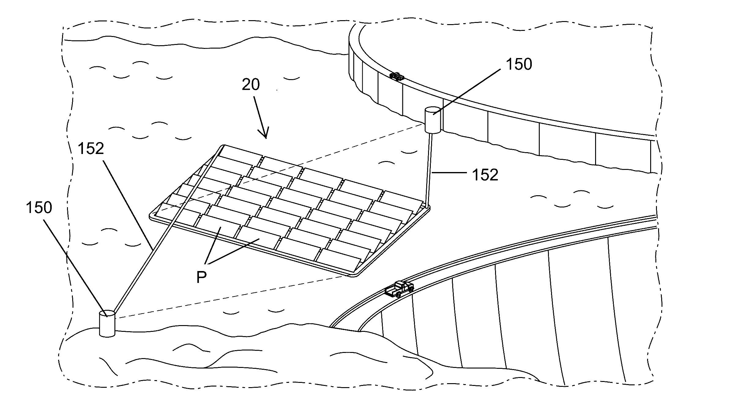
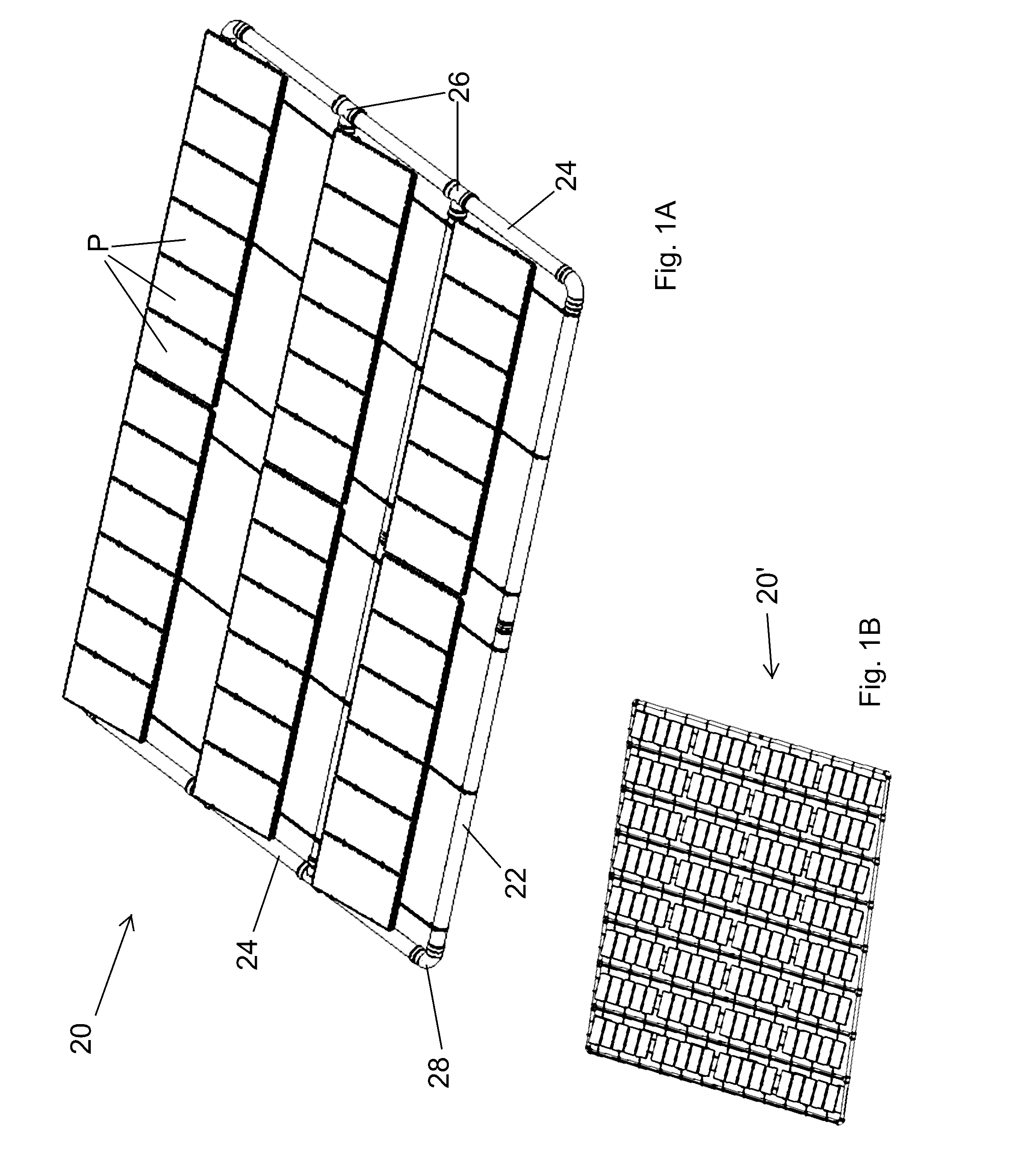
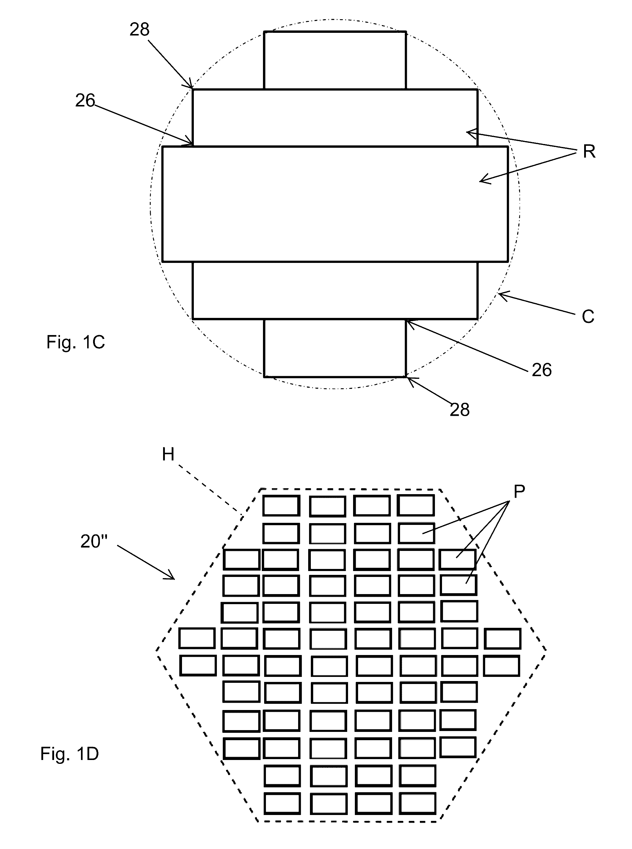
[0038]The present application discloses an or several arrays of floating solar panels with a one-axis tracking system to cause the panels to face the sun at all times of the day. The solar panels are mounted over a series of connected rows and columns of buoyant flexible pipes forming a buoyant closed loop shape around an outer periphery.

[0039]The arrays of floating solar photovoltaic panels may be utilized on lakes, water dams, mine tailings or other water reservoirs. The arrays may also later be deployed on the sea water in calm areas. The panels are installed by floating arrays composed of a large number of panels, typically around 1,000 panels. Each array is made of parallel lines of flexible pipes, making a closed loop shape on an outer periphery of flexible pipes. The flexible pipes are connected by electro-welded or thermo-welded fittings with elbow connections at corner junctions of two pipes and T-fittings at junctions of three pipes, as will be seen. Each array is holding ...


PUM


Abstract

A floating solar array made of a closed loop of flexible high density polyethylene pipes with elbows, T fittings and couplings. An anti-lift membrane fills with water and mitigates the wind forces. The array can have a stabilizing skirt going downwardly from the border of the array, especially when it is used offshore in the sea. A vertical axis tracking system with windlasses, two anchoring points and four mooring lines allows all the solar panels to face the sun throughout the day. For small lakes or mine tailing, the two anchor points will be onshore, on a concrete foundation. Winches to wind and unwind the mooring lines are located at the anchor point or on the solar array. For larger water areas, or offshore applications in the sea water, the anchor points are under water; using typically a concrete block or a suction pile solution for each anchor.

Description

RELATED APPLICATIONS[0001]The present application claims priority under 35 U.S.C. 119 to U.S. Provisional Application No. 62 / 339,844, filed May 21, 2016, and to U.S. Provisional Application No. 62 / 200,420, filed Aug. 3, 2015.FIELD OF THE INVENTION[0002]The present application pertains to photovoltaic systems and, more particularly, to a system of floating solar panels with a one-axis tracking system to cause the panels to face the sun at all times.BACKGROUND OF THE INVENTION[0003]During the next decades, the generation of sustainable energy will become one of the main challenges of our civilization. Worldwide energy demand is expected to grow from about 10 GTep (1010 Tep [Ton Equivalent Petrol], or 5*1019 Joule) in the beginning of the century to 15-20 GTep by 2050. Some scenarios predict even levels as high as 40 GTep. An analysis of future global petrochemical consumption needs (i.e. energy needs and / or raw material for chemical industry) implies that early petrol shortages might ...

Claims


Application Information

Patent Timeline
IPC IPC(8): H02S10/40H02S20/32H02S30/10
CPCH02S10/40H02S20/32H02S30/10F24S20/70F24S30/422F24S2030/133H02S20/00H02S20/30Y02E10/47Y02E10/50
Inventor SMADJA, LILIANESMADJA, PAUL ISAAC
Owner 4CSOLAR
Why Eureka
Try Eureka