
Marine engine propelling apparatuses

a technology for propelling apparatuses and engines, which is applied in the direction of marine propulsion, propulsive elements, and vessel construction, etc., can solve the problems of increasing the risk of power loss, complicated production or manufacturing management of engine propelling apparatuses, and complex s-shaped power transmission routes of motors, so as to improve fuel efficiency and maintenance. , the effect of improving fuel efficiency

Active Publication Date: 2017-02-16
TOYOTA IND CORP +1
View PDF5 Cites 5 Cited by
  • Summary
  • Abstract
  • Description
  • Claims
  • Application Information

AI Technical Summary

Benefits of technology

The patent describes a problem with traditional marine engine propelling apparatuses. These apparatuses are heavy and have a complex power transmission route, which leads to power loss. This results in difficulty in making the motor small or lightweight. Additionally, the apparatuses come in different heights, which makes it difficult to manage production and manufacturing. Therefore, the patent aims to create a marine engine propelling apparatus that is simple in structure, efficient in power transmission, and lightweight.

Problems solved by technology

In addition to the large number of components, the motor has a complex S-shaped power transmission route.
This causes an increased risk of loss of power.
This height variation complicates the production or manufacturing management of the engine propelling apparatus, and may further prevent a reduction in the size or weight of the engine propelling apparatus.

Method used


Image

  • Marine engine propelling apparatuses
  • Marine engine propelling apparatuses
  • Marine engine propelling apparatuses

Examples


Embodiment Construction

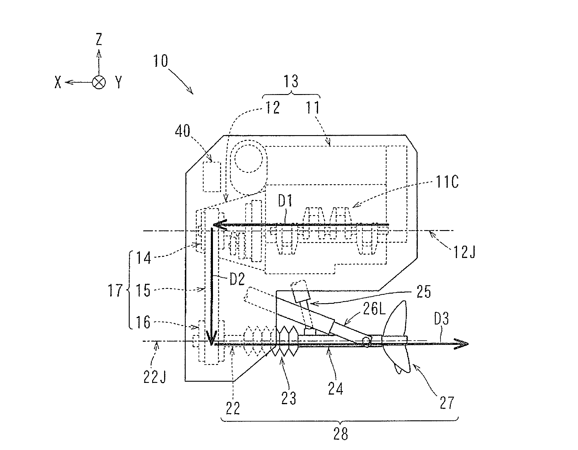
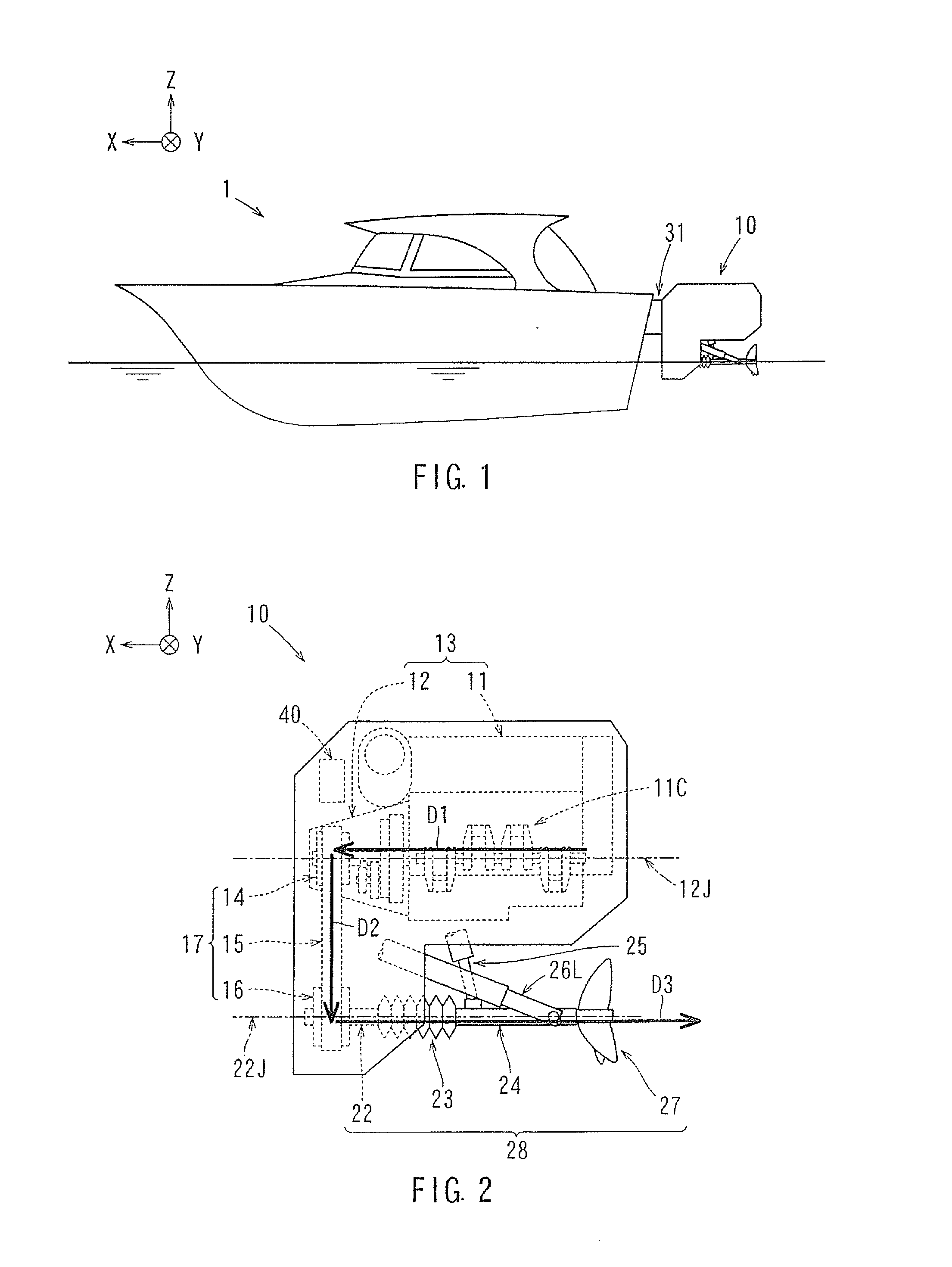
[0032]A marine engine propelling apparatus 10, 10A and 10B according to an embodiment of the present invention will be described with reference to the drawings. For purposes of this application, and as used hereinafter, an X-direction is defined as a front direction in which a boat advances where the front-rear direction of the boat lies in and defines the X-axis, a Y-direction is defined as the right direction of the boat where the right-left direction of the boat lies in and defines the Y-axis, and a Z-direction is defined as the vertical and upward direction relative to the longitudinal axis of the boat, where the upward-downward direction of the boat lies in and defines the Z-axis. The right-left direction mentioned below is determined relative to the direction in which the boat advances, or relative to the state of the boat as seen from behind, wherein the direction in which the boat advances and from which it can be seen from behind is along the X-axis.

[0033]As shown in FIG. 1...


PUM


Abstract

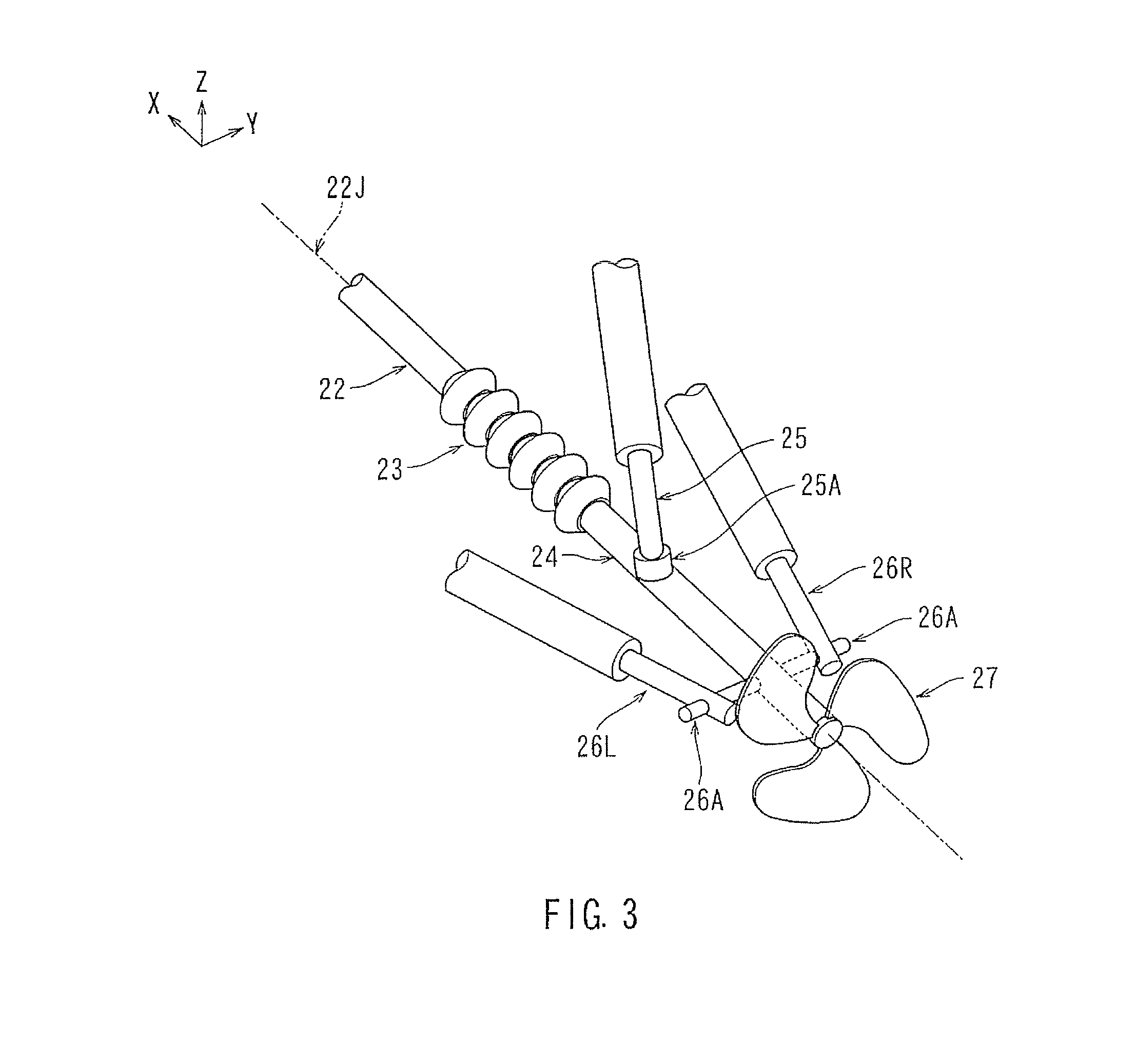
A marine engine propelling apparatus (10) is mounted to an outboard portion at a rear end of a boat. The engine propelling apparatus (10) has a power generating portion (13), a power transmitting portion (17) provided below the power generating portion (13), a propelling force generating portion (28) provided below the power transmitting portion (17), and a height adjustment mechanism (25). The power generating portion (13) includes an engine (11) equipped with a crankshaft (11C), and the crankshaft (11C) is arranged substantially parallel to a front-rear direction of the boat and is substantially horizontal. The power transmitting portion (17) has a power transmission mechanism forming a linear power transmission route (D2) extending from the vicinity of a front end of the crankshaft (11C) to the vicinity of a front end of the propelling force generating portion (28). The propelling force generating portion (28) includes a propeller shaft (22) extending rearwards from the power transmitting portion (17), and a propeller (27) provided at a rear portion of the propeller shaft (22). The height adjustment mechanism (25) is configured to vary inclination of a part of the propeller shaft (22) with respect to the boat to thereby vary height of the propeller (27) with respect to the boat.

Description

CROSS-REFERENCE TO RELATED APPLICATIONS[0001]The present application is a National Phase entry of, and claims priority to, PCT Application No. PCT / JP2015 / 060583, filed Apr. 3, 2015, which claims priority to Japanese Patent Application No. 2014-085482, filed Apr. 17, 2014, both of which are incorporated herein by reference in their entireties for all purposes.BACKGROUND[0002]The present invention relates to a marine engine propelling apparatus which is mounted, for example, to an outboard portion at a rear end of a boat.[0003]A marine engine propelling apparatus is mounted to an exterior portion at a rear end of a boat used, for example, for fishing or cruising. There exist a variety of engine propelling apparatuses according to the size of the boat or the height of the rear end of the boat as measured from the water surface, etc.[0004]Japanese Laid-Open Patent Publication 2013-519574 discloses a large marine outboard motor. The large marine outboard motor 110, as shown in FIG. 15, i...

Claims


Application Information

Patent Timeline
IPC IPC(8): B63H20/14B63H20/06B63H23/34B63H25/06B63H20/28B63H20/10B63H25/42
CPCB63H20/14B63H20/10B63H20/06B63J2099/006B63H25/06B63H20/28B63H23/34B63H25/42B63H20/22B63H2001/185B63B79/10Y02T70/10
Inventor KOMODA, MASAHIROSUGIURA, YOSHIMITSUISOBE, YUSHIRO
Owner TOYOTA IND CORP
Learn More