Bearing structure and turbocharger

Active Publication Date: 2017-02-16
IHI CORP
View PDF6 Cites 3 Cited by
  • Summary
  • Abstract
  • Description
  • Claims
  • Application Information

AI Technical Summary

Benefits of technology

The present patent aims to improve the performance of bearings and reduce vibration. This is achieved through the use of a bearing structure and a turbocharger that work together to achieve better performance and reduce vibration.

Problems solved by technology

Consequently, the temperature of lubricating oil may rise to thereby deteriorate bearing performance.

Method used


Image

  • Bearing structure and turbocharger
  • Bearing structure and turbocharger
  • Bearing structure and turbocharger

Examples


Embodiment Construction

[0020]Hereinafter, an embodiment of the present disclosure will be explained in detail with reference to the attached drawings. Dimensions, materials, concrete numerical values etc. shown in such embodiment are nothing but exemplifications for making understanding of the disclosure easy, and do not limit the present disclosure unless otherwise noted in particular. Note that, in the description and drawings, to components having substantially the same function or configuration, the same sign is attached and repeated explanation is omitted, and diagrammatic representation of components having no direct relationship to the present disclosure is omitted.

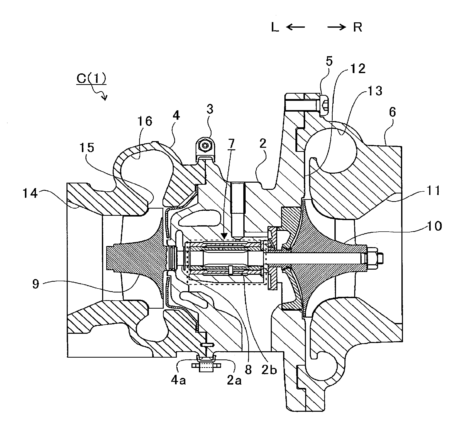
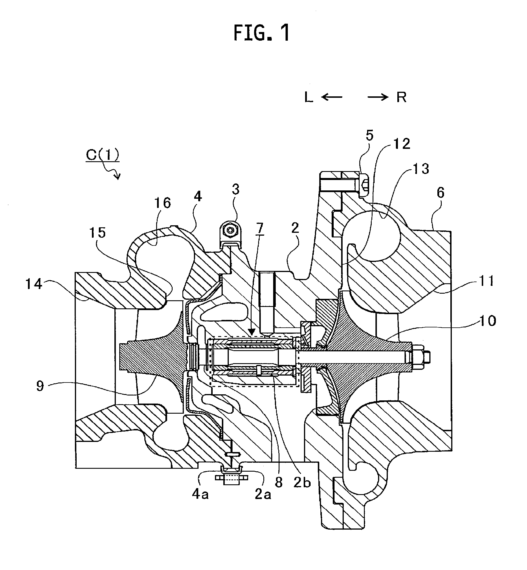
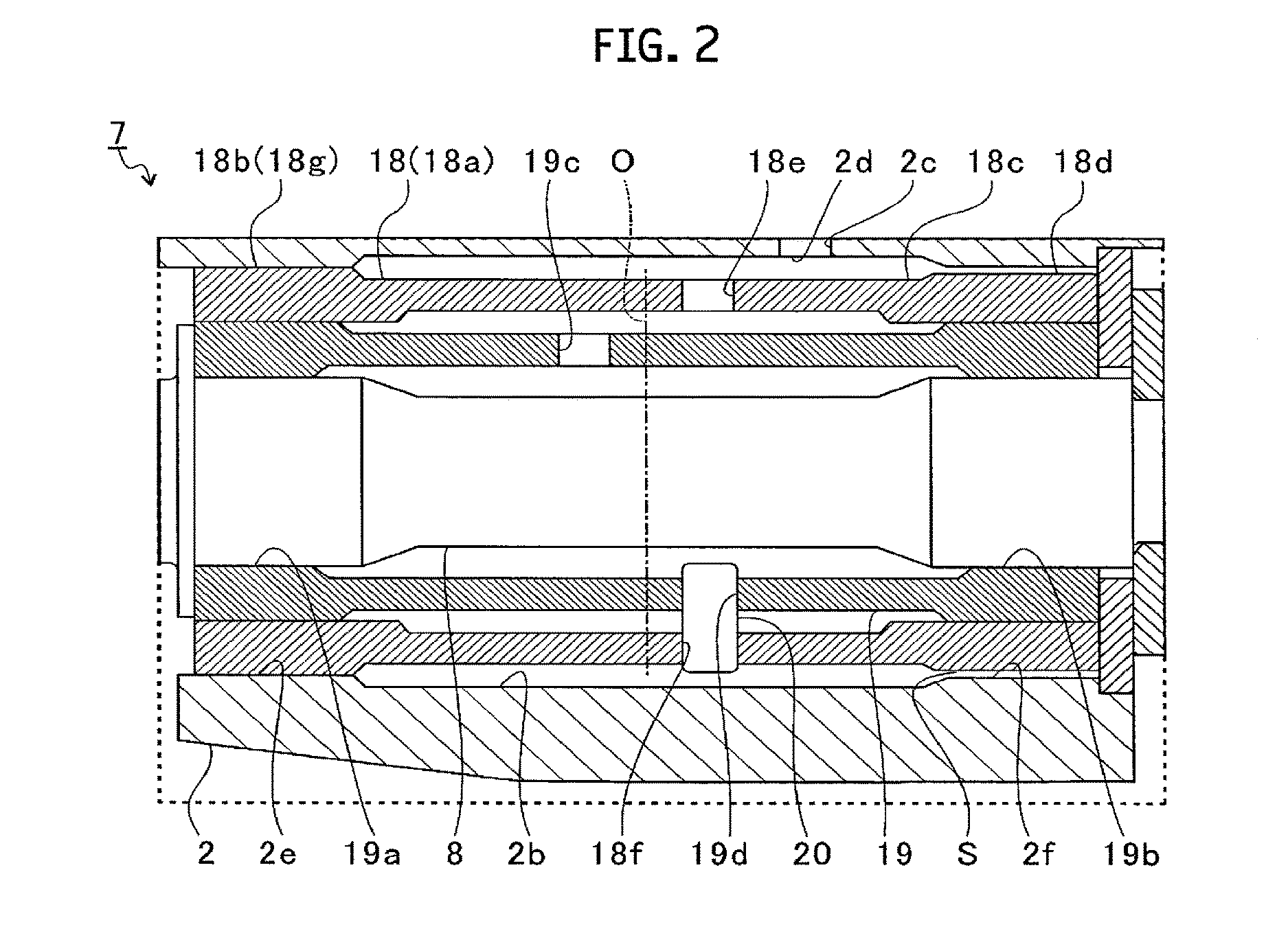
[0021]FIG. 1 is a schematic cross-sectional view of a turbocharger C. In what follows, explanation will be given with a definition that an arrow L shown in FIG. 1 shows the direction of the left side of the turbocharger C, and that an arrow R shows the direction of the right side of the turbocharger C. As shown in FIG. 1, the turbocharge...


PUM


Abstract

A bearing structure includes a through-hole penetrating through in the axial direction of shaft, a bearing holder accommodated in the through-hole, a semi-floating metal bearing accommodated in the bearing holder and supporting the shaft inserted into the inside, and a positioning member being inserted into a radial direction of the shaft for both the bearing holder and the semi-floating metal bearing and regulating movement of the semi-floating metal bearing in the axial direction and in a rotating direction of the shaft relative to the bearing holder. For the bearing holder, a press-fit portion to be press-fitted into the through-hole is formed. A gap is formed between at least one of outer circumferential surfaces of both end parts of the bearing holder in the axial direction and the inner circumferential surface of the through-hole.

Description

CROSS REFERENCE TO RELATED APPLICATIONS[0001]This application is a continuation application of International Application No. PCT / JP2015 / 068493, filed on Jun. 26, 2015, which claims priority to Japanese Patent Application No. 2014-141173, filed on Jul. 9, 2014, the entire contents of which are incorporated by reference herein.BACKGROUND[0002]1. Technical Field[0003]The present disclosure relates to a bearing structure in which a shaft is supported by a semi-floating metal bearing, and to a turbocharger.[0004]2. Description of the Related Art[0005]Heretofore, there is known a turbocharger in which a shaft is supported rotatably by a bearing housing and the shaft is provided with a turbine wheel at one end of the shaft and a compressor wheel at the other end of the shaft. Such turbocharger is connected to an engine, and the turbine wheel is rotated by exhaust gas discharged from the engine, and the compressor wheel is rotated by the rotation of the turbine wheel via the shaft. In this ...

Claims


Application Information

Patent Timeline
IPC IPC(8): F01D25/16F04D29/28F04D29/063F04D29/053F01D25/18F01D5/04F04D29/056
CPCF01D25/162F01D5/04F04D29/284F04D29/056F05D2300/10F01D25/18F04D29/063F05D2220/40F05D2240/60F04D29/053F16C17/02F16C33/10F16C17/18F16C27/02F16C2360/24F04D29/0563F04D29/057F01D25/164
Inventor UNEURA, YUTAKAKANEDA, SHINICHIDAITO, YUICHIKOJIMA, HIDEYUKISUGIURA, TOMOMI
Owner IHI CORP
Why Eureka
Try Eureka