Rotating beacon

a technology of rotating beacons and beams, which is applied in the direction of fixed installation, semiconductor devices for light sources, lighting and heating apparatus, etc., can solve the problems of large clutter in the space available for ventilation, and apply a fraction of available intensity, and achieve high lumen output, high efficacy, and high power

Active Publication Date: 2017-02-16
ORION SAFETY & CONTROL SYST PTY LTD
View PDF4 Cites 7 Cited by
  • Summary
  • Abstract
  • Description
  • Claims
  • Application Information

AI Technical Summary

Benefits of technology

[0025]The light emitting diode (LED) assembly may be a high power, multiple-semiconductor-device. For example, the LED assembly may be the metallic chassis, multiple-bead arrangeme

Problems solved by technology

This has the disadvantage in a beacon of only applying a fraction of the available intensity at any one time

Method used


Image

  • Rotating beacon
  • Rotating beacon
  • Rotating beacon

Examples


Embodiment Construction

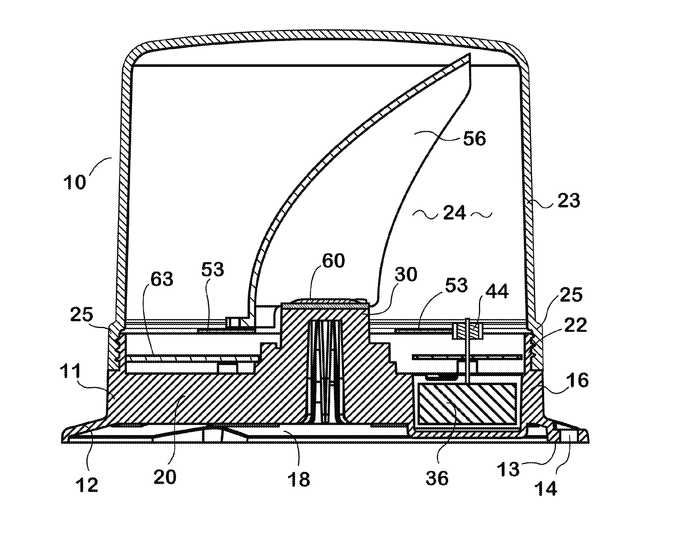
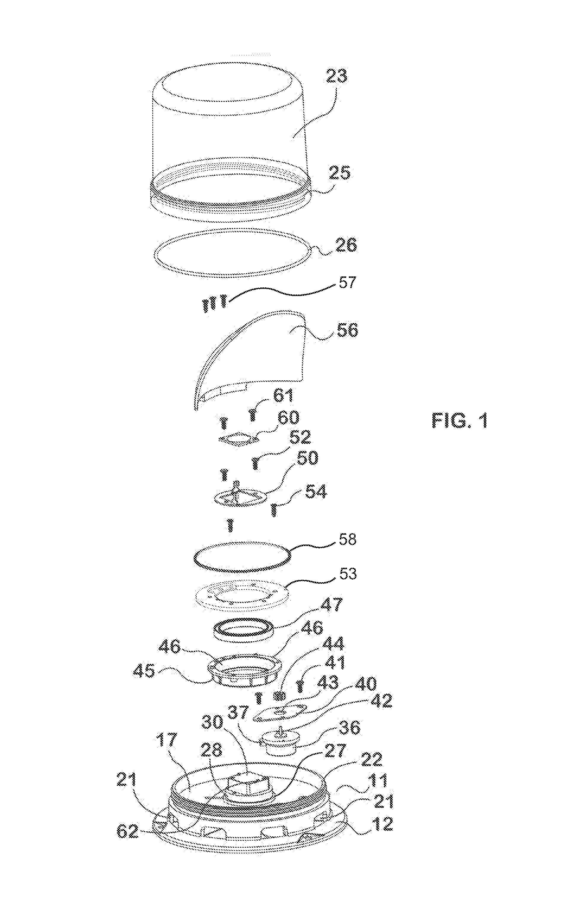
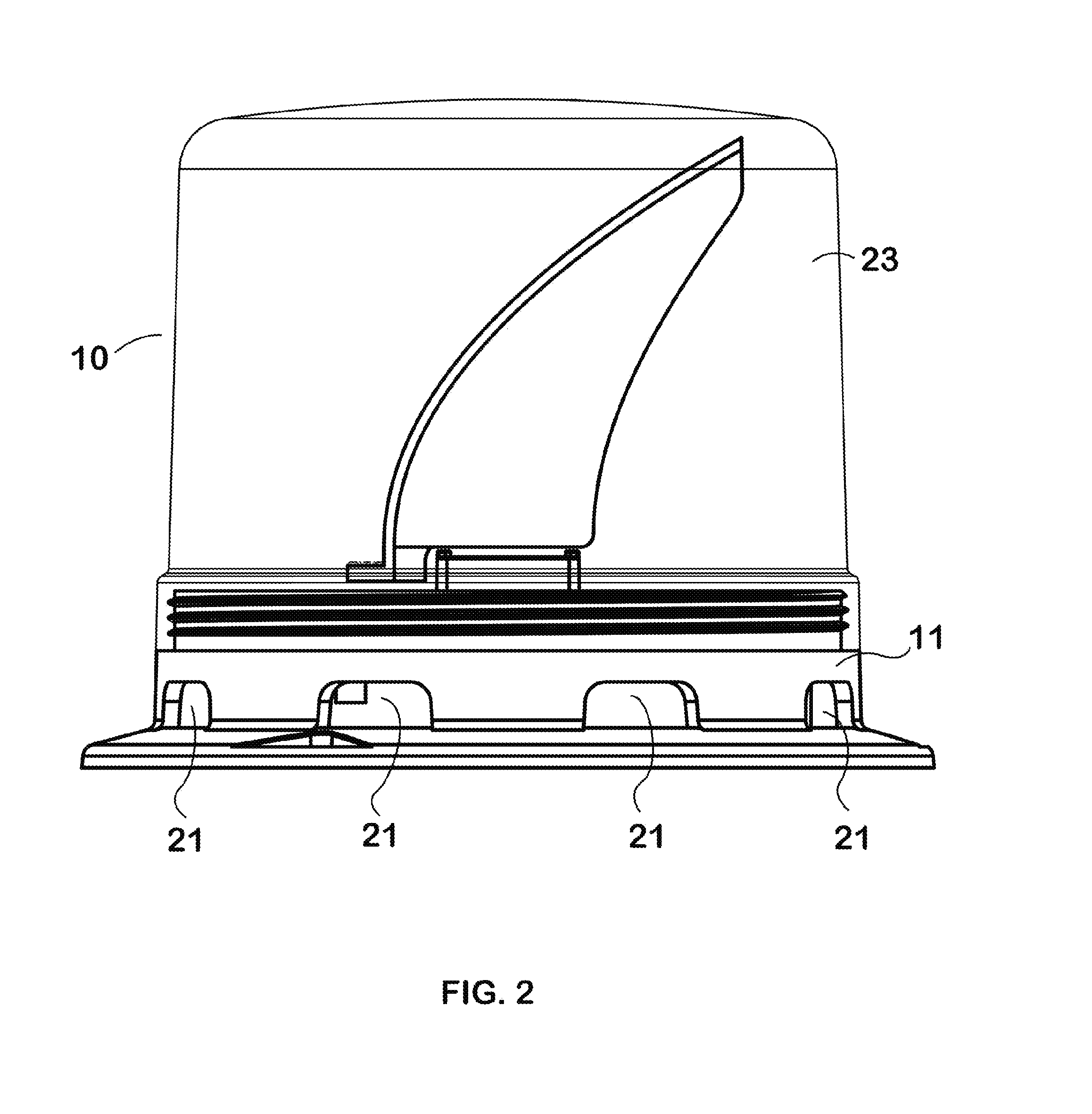
[0040]In the FIGS. 1 to 6 there is provided a beacon assembly 10 including a mounting base 11 of cast aluminium alloy. The mounting base 11 is an integral, one-piece casting having formed therein a mounting flange 12 incorporating mounting pads 13 and bolt holes 14. The mounting flange is bounded at its inner periphery 15 by a side wall portion 16, which is closed over intermediate its height by an upper wall portion 17 to form a lower chamber 18. The side 16 and upper 17 wall portions support integrally formed cooling fins 20. The side wall portion 16 is relieved by eight ventilation ports 21. The casting is provided with alternative threaded mounting bolt posts 19 for enabling the base 11 to be blind-fixed from below.

[0041]The side wall portion 16 extends above the upper wall portion 17 to provide a substantially cylindrical mounting spigot 22 on which is supported a polycarbonate transparent housing 23 and which forms, with the mounting base 11, an upper chamber 24. The mounting ...


PUM


Abstract

There is provided a beacon assembly (10) including an integral cast metal mounting base (11) having a mounting flange (12) bounded by a ventilated side wall portion (16) and an upper wall portion (17) combining to support integral cooling fins (20). The side wall portion (16), transparent housing (23) and mounting base (11) form an upper chamber (24). An integrally formed motor housing portion (32) supports a synchronous DC motor (36) driving an input spur gear (44) meshed with a carrier (53) and gear belt (58) assembly supporting a metallized polymer parabolic reflector (56). The thermal mount (30) mounts an LED Array (60) using thermal paste at the reflector (56) focal point.

Description

FIELD OF THE INVENTION[0001]This invention relates to rotating beacons. This invention has particular application to rotating beacons for vehicular use, and for illustrative purposes the invention will be described with reference to this application. However, it is envisaged that this invention will find application in for example warning devices on fixed installations.BACKGROUND OF THE INVENTION[0002]Rotating beacons have been a mainstay of emergency service vehicles for many years. In its most fundamental a rotating beacon comprises a continuous light source that is focused into a beam and is either rotating or, more commonly, is located at the focus of a rotating reflector. The focussing element is most usually a parabolic reflector.[0003]A rotating reflector may comprise the focussing element, but need not necessarily be so. For example, a parabolic focussing reflector may direct a beam into a rotating plane mirror. The optical parts are generally housed in an optically transpar...

Claims


Application Information

Patent Timeline
IPC IPC(8): F21V14/04F21V29/89F21V29/77B60Q1/52F21V17/14F21V31/00F21S8/10B60Q1/26F21V7/06F21V29/83
CPCF21V14/04F21V7/06F21V29/89F21V29/77F21V29/83F21Y2115/10F21V31/005F21S48/234F21S48/328B60Q1/2611B60Q1/52F21V17/14F21S10/063
Inventor MCNICOL, MARCHUANG, ZHIQIANG
Owner ORION SAFETY & CONTROL SYST PTY LTD
Why Eureka
Try Eureka