Liveness detection

a technology of living entities and detection methods, applied in the field of living entities, can solve the problem that non-living entities have very difficult to replicate accurately reactions,

Inactive Publication Date: 2017-02-16
YOTI HLDG LTD
View PDF0 Cites 19 Cited by
  • Summary
  • Abstract
  • Description
  • Claims
  • Application Information

AI Technical Summary

Benefits of technology

[0012]The inventors of the described technology have recognized that physiological responses to randomized outputs (such as randomized visual or audible outputs), as exhibited by visible human features (such as the eyes or mouth), provide an excellent basis for liveness detection, as such reactions are very difficult for non-living entities to replicate accurately.

Problems solved by technology

The inventors of the described technology have recognized that physiological responses to randomized outputs (such as randomized visual or audible outputs), as exhibited by visible human features (such as the eyes or mouth), provide an excellent basis for liveness detection, as such reactions are very difficult for non-living entities to replicate accurately.

Method used


Image

  • Liveness detection
  • Liveness detection
  • Liveness detection

Examples


first embodiment

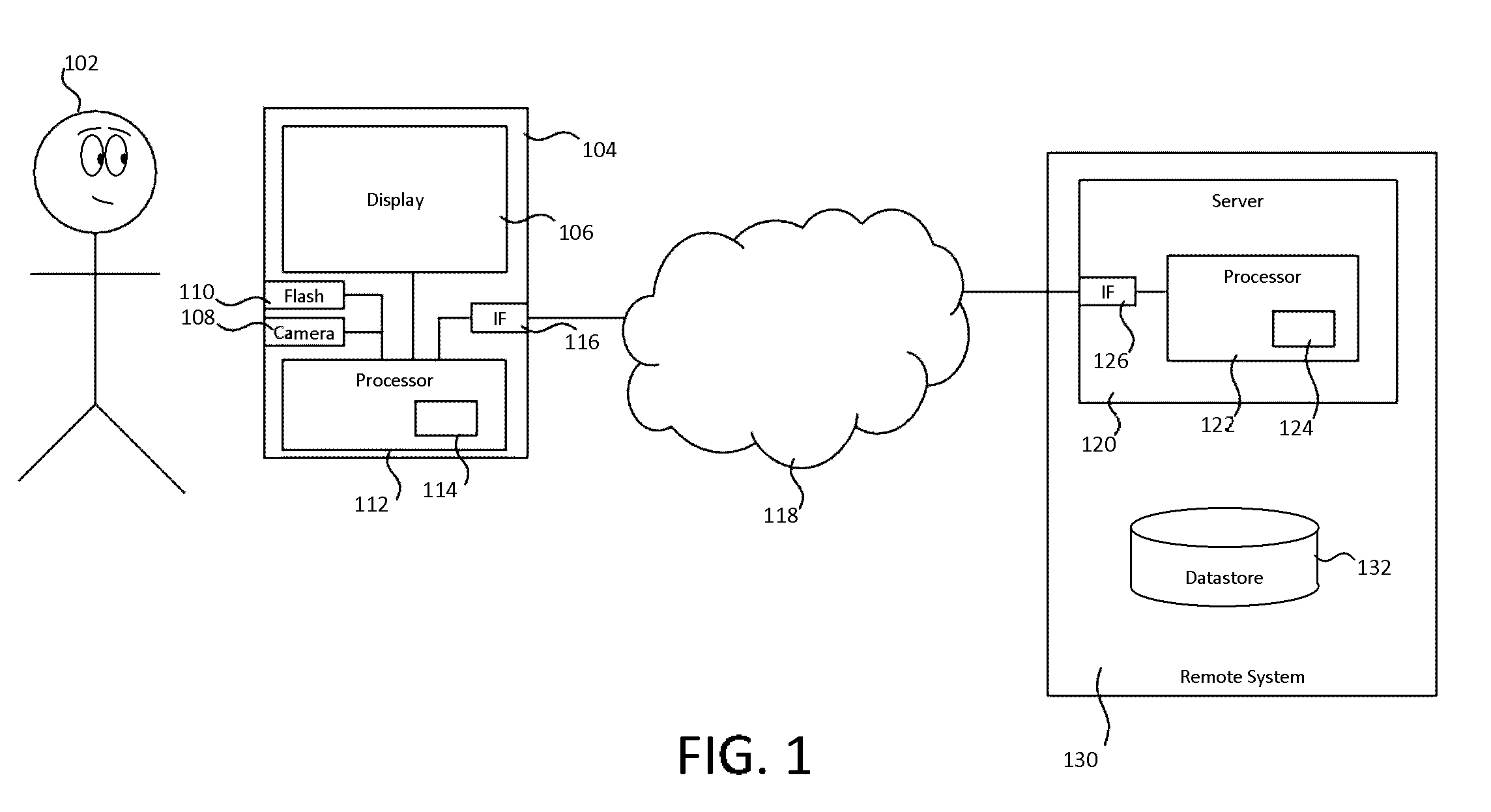
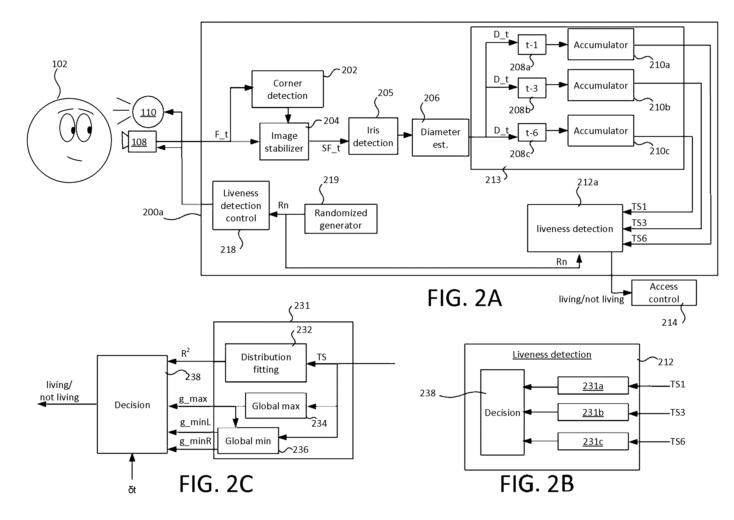
[0099]FIG. 2A shows a liveness detection system 200a in the described technology. The liveness detection system 200a comprises the following functional modules: a liveness detection controller 218 connected to control the camera 108 and flash 110 (or alternatively the display 106); an image stabilizer 204 having an input connected to receive a video signal from the camera 204; a corner detector 202 having an input connected to receive the video signal and an output connected to the image stabilizer 204; an iris detector 205 having an input connected to receive a stabilized version of the image signal from the image stabilizer 204; a diameter estimator 206 having an input connected to an output of the iris detector 206 and an output; first second and third time differential modules 208a, 208b, 208c, each having a respective input connected to the output of the diameter estimation module 206; first, second and third accumulators 210a, 210b, 210c having respective inputs connected to t...

second embodiment

[0154]FIG. 6B shows a block diagram of a liveness detection system 200b in a The system 200b implements a technique for anti-spoofing based on tracking the iris movement by presenting elements at random positions of the screen.

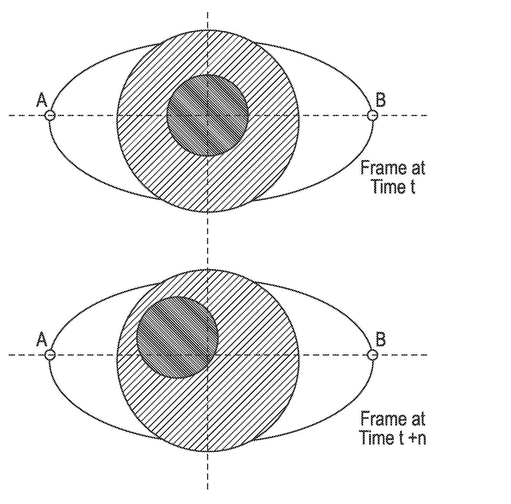
[0155]In the second embodiment, in a liveness test performed according to Rn, the liveness detection controller controls the display 106 and the camera 108 of the user device. In the second embodiment, the liveness detection controller uses randomized data Rn generated by the randomized generator 219 to display randomized display elements at randomized locations on the display 106 in a liveness detection test. The randomized data Rn is in the form of one or more parameters that define the display locations, referred to as an eye tracking (“ET”) parameter set in the context of the second embodiment.

[0156]The corner detector 202, image stabilizer 204 and iris detector 205 are connected as in the first embodiment, and perform the same operations. The system 200b...

third embodiment

[0203]In the third embodiment, importantly, the randomness of the process is generated server-side.

[0204]After receiving the PD parameters from the pupil dilation server 120b (S1104a) and the ET parameters from the eye tracking server 120c (S1104b), the liveness server 120a transmits the PD and ET parameters to the user device 104.

[0205]At step S1107 user device 104 uses the PD and ET parameters to instigate the liveness detection processes of the first and second embodiments respectively by performing the randomized pulse test according to the PD parameters and the randomized display element test according to the ET parameters i.e. emitting light pulses at random interval(s) based on the PD set and displaying display element(s) at random locations selected on the user's curve Cv based on the ET parameter set. This may be triggered by the liveness server 120a requesting a liveness check from the user device 106, or the user device requesting a liveness detection check form the liven...


PUM


Abstract

A liveness detection system comprises a controller, a video input, a feature recognition module, and a liveness detection module. The controller is configured to control an output device to provide randomized outputs to an entity over an interval of time. The video input is configured to receive a moving image of the entity captured by a camera over the interval of time. The feature recognition module is configured to process the moving image to detect at least one human feature of the entity. The liveness detection module is configured to compare with the randomized outputs a behaviour exhibited by the detected human feature over the interval of time to determine whether the behaviour is an expected reaction to the randomized outputs, thereby determining whether the entity is a living being.

Description

INCORPORATION BY REFERENCE TO ANY PRIORITY APPLICATIONS[0001]The following applications are incorporated herein by reference in their entirety:Application No.TitleDate Filed14 / 622,740AUTHENTICATION OF WEBFeb. 13, 2015CONTENT14 / 622,527DIGITAL IDENTITYFeb. 13, 201514 / 622,737DIGITAL IDENTITYFeb. 13, 201514 / 622,549CONFIDENCE VALUESFeb. 13, 201514 / 622,709DIGITAL IDENTITY SYSTEMFeb. 13, 2015## / ###,###LIVENESS DETECTIONAug. 10, 2015BACKGROUND OF THE INVENTION[0002]Field[0003]The described technology is in the field of liveness detection, and has particular applications in the context of network security to prevent spoofing attacks based on entities masquerading as humans.[0004]Description of the Related Art[0005]In the context of network security, a spoofing attack refers to a technique whereby an unauthorized human or software entity masquerades as an authorized entity, thereby gaining an illegitimate advantage.[0006]A particular example is an unauthorized entity masquerading as a particu...

Claims


Application Information

Patent Timeline
Patent Type & Authority Applications(United States)
IPC IPC(8): G06K9/00G06K9/62G06K9/46G06T7/20G06K9/52G06V10/50
CPCG06K9/00906G06K9/00617G06T7/20G06K9/0061G06T2207/20021G06K9/4642G06K9/4661G06K9/6267G06K9/00758G06K9/52G06T2207/10016G06T2207/30201G06T7/246G06V40/19G06V40/45G06V10/467G06V10/50G06V10/54
Inventor RODRIGUEZ, FRANCISCO ANGEL GARCIAPARASKEVAS, GEORGIOSLOUGHLIN-MCHUGH, ELEANOR SIMONE FREDERIKAKHAN, USMAN MAHMOODTREMOULHEAC, BENJAMIN ROBERT
Owner YOTI HLDG LTD
Why Eureka
Try Eureka