Power conversion device connected to single-phase system

Active Publication Date: 2017-02-16
KAWASAKI HEAVY IND LTD
View PDF8 Cites 23 Cited by
  • Summary
  • Abstract
  • Description
  • Claims
  • Application Information

AI Technical Summary

Benefits of technology

[0029]The present invention makes it possible to provide a power conversion device connected to a single-phase system and capable of causing the single-phase system to perform self-sustained operation by virtual synchronous gene

Problems solved by technology

However, there are cases assuming both the interconnected operation and self-sustained o

Method used


Image

  • Power conversion device connected to single-phase system
  • Power conversion device connected to single-phase system
  • Power conversion device connected to single-phase system

Examples


embodiment 1

Configuration

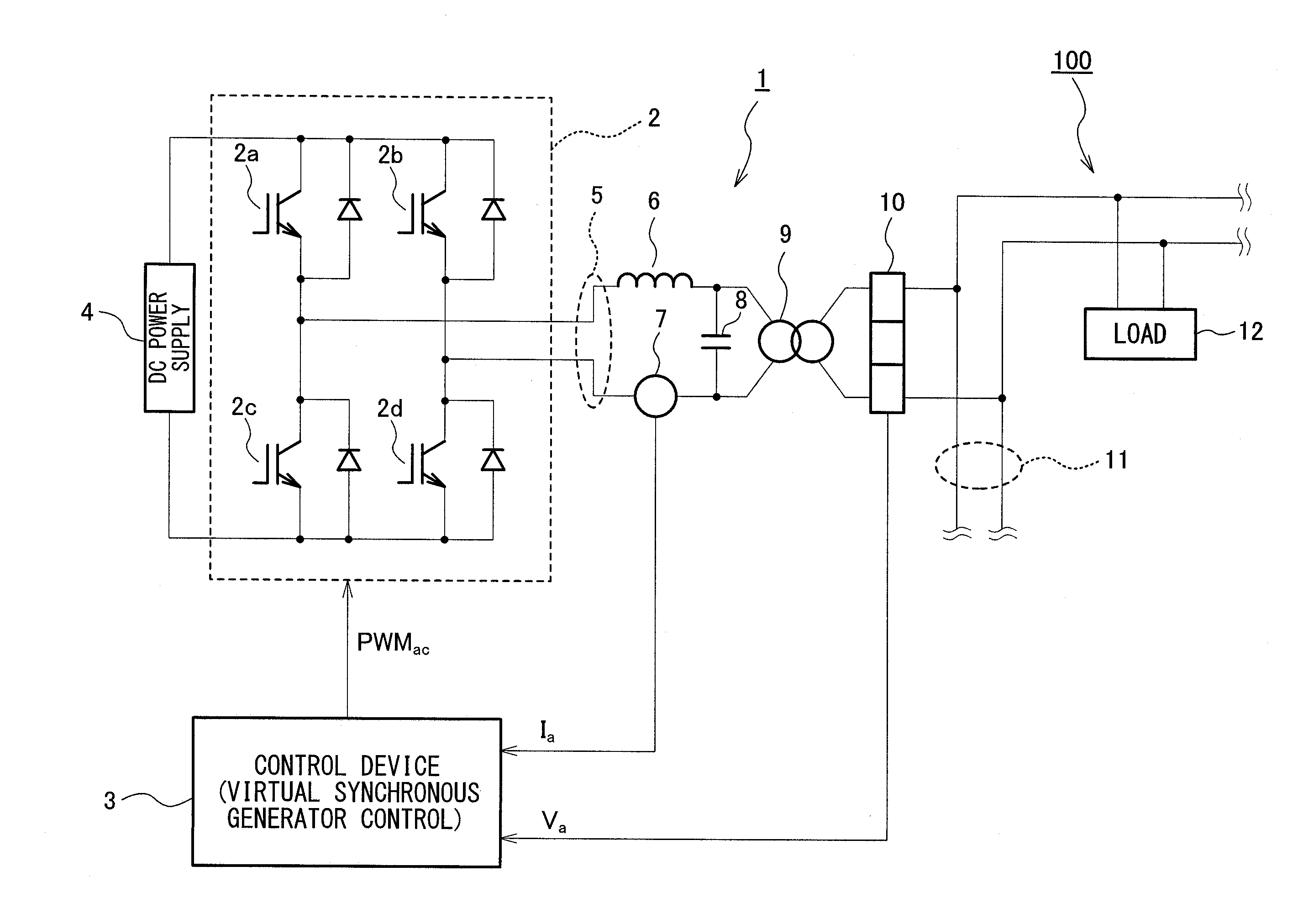
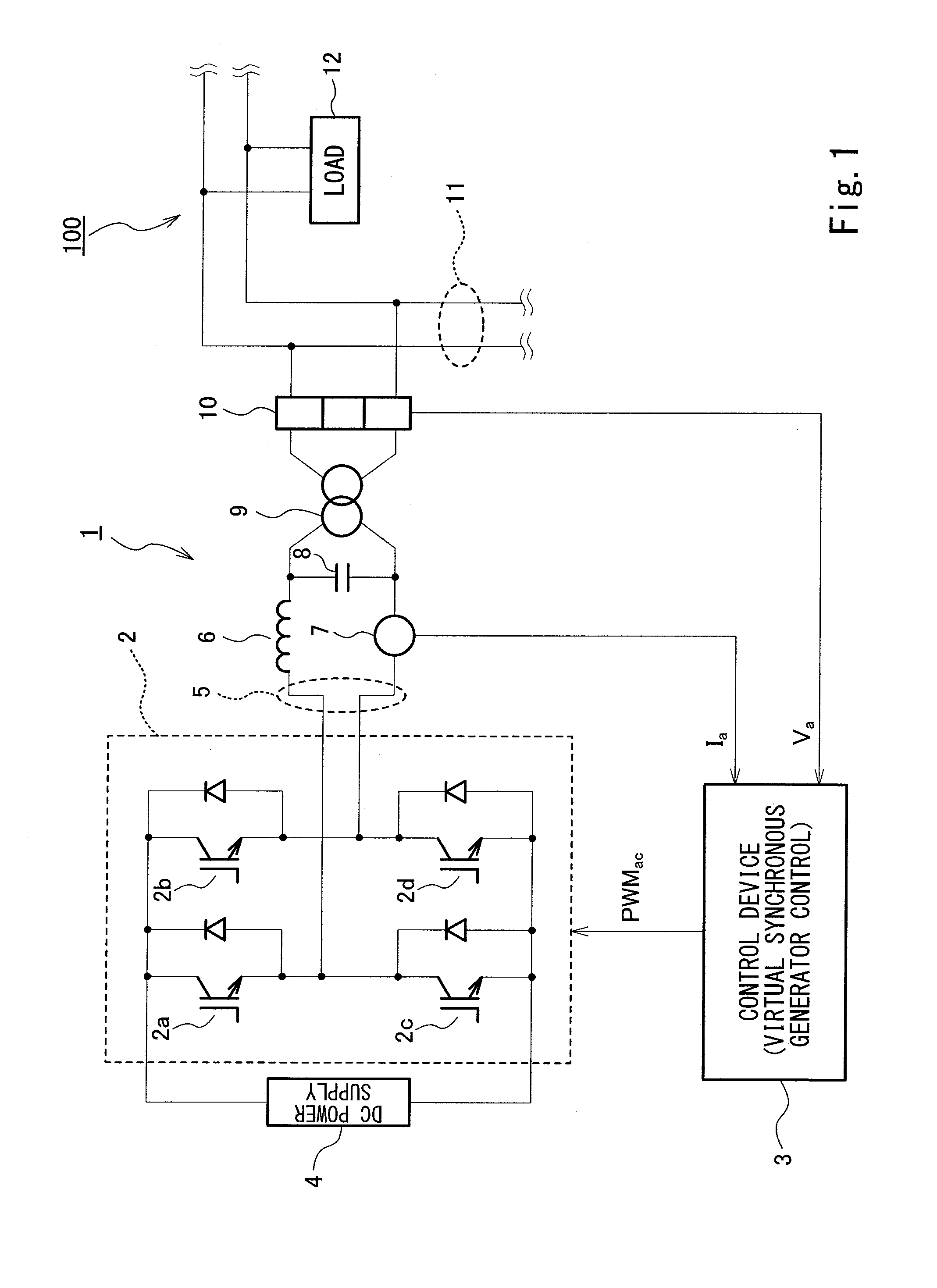
[0047]FIG. 1 is a block diagram showing the configuration of a power conversion device according to Embodiment 1 of the present invention. As shown in FIG. 1, a power conversion device 1 is, for example, connected to a single-phase power system 100, which is a microgrid, via output lines 5, an output reactor 6, a current sensor 7, a filter capacitor 8, a transformer 9, and a voltage sensor 10. In the present embodiment, power distribution lines 11 of the single-phase power system 100 are two distribution lines forming single-phase two-line wiring (100 V). Alternatively, the power distribution lines 11 may be three distribution lines forming single-phase three-line wiring (100 V / 200 V). Examples of the single-phase power system 100 include: a power distribution network for detached houses, apartments, offices, etc.; a power system of a vessel; an electrical grid of an isolated island; and a power system of a factory or the like equipped with a private power generating fa...

verification experiment

[Verification Experiment]

[0108]The inventors of the present invention conducted an experiment under predetermined conditions for the purpose of verifying the advantages of the power conversion device 1 of the present embodiment. FIG. 10 is a schematic diagram of a test system for the power conversion device 1. As shown in FIG. 10, the test system includes: a commercial single-phase electrical grid 101; the power conversion device 1 connected to the commercial single-phase electrical grid 101; a single-phase power system 100′ simulating a microgrid; switches MC1 to MC4; and a monitoring device 200, which supplies an active power command value Pref and a reactive power command value Qref to the power conversion device 1. The single-phase power system 100′ includes only loads 12a to 12d of the power conversion device 1.

[0109]The fundamental frequency of each of the commercial single-phase electrical grid 101 and the single-phase power system 100′ is 60 Hz. The rated capacity of the pow...

embodiment 2

[0120]Next, Embodiment 2 of the present invention is described with reference to FIG. 13 and FIG. 14. In Embodiment 2, the description of configurations common between Embodiment 1 and Embodiment 2 are omitted, and differences in configuration from Embodiment 1 are only described in Embodiment 2.

[0121]Embodiment 2 is different from Embodiment 1 in that, in Embodiment 2, feedback control of the single-phase system current is performed by using d-axis and q-axis components of the system current that are obtained based on FAE (Fictive Axis Emulation) operation.

[0122]FIG. 13 is a block diagram showing the configuration of current feedback control of a power conversion device according to Embodiment 2 of the present invention. As shown in FIG. 13, a current controller 26a is configured to generate an α-axis voltage command value Vα_ref and a β-axis voltage command value Vβ_ref of a rest frame based on feedback current values Idq and the current command values Idq_ref calculated by the ge...


PUM


Abstract

A power conversion device includes: a power converter to perform output to an output line connected to a single-phase power system; and a control device to control the power converter so it operates as a virtual synchronous generator. The control device includes: a voltage and current measurer to obtain, from a single-phase system voltage, an angular velocity and a phase of the system voltage by an estimation operation that uses the phase of the system voltage as a parameter; a power obtainer to obtain active power and reactive power; a governor model to calculate a phase difference; an AVR model to calculate an absolute value of an induced voltage of a virtual synchronous generator; a generator model to calculate current command values corresponding to an armature current of the virtual synchronous generator; and a current controller to generate and output a PWM signal to the power converter.

Description

TECHNICAL FIELD[0001]The present invention relates to a power conversion device connected to a single-phase system, and particularly to a power conversion device capable of virtual synchronous generator control.BACKGROUND ART[0002]In recent years, power supply systems utilizing distributed power supplies such as gas engine generators and fuel cells are drawing increasing attention. For example, there is one proposed system that uses a power generator called a distributed power supply mentioned above to supply electric power from the power generator to a plurality of electrical loads in a particular area. Such a system, which is called a micro grid, is often configured such that a power system therein is connected not only to the aforementioned power generator but also to an energy storage that is equipped with, for example, a secondary battery. The energy storage is provided for compensating for fluctuations in power generation by the power generator as well as load variations. Ther...

Claims


Application Information

Patent Timeline
IPC IPC(8): H02M7/537
CPCH02M7/537H02M1/42H02M7/53871H02M7/5395Y02E40/30H02J3/18Y02B70/10H02J3/38
Inventor SAKIMOTO, KENICHIHIRASE, YUKOYOSHIMURA, EIJIKATSURA, SHOGONAKAGAWA, HIDEHIKONORO, OSAMUSHINDO, YUJI
Owner KAWASAKI HEAVY IND LTD
Why Eureka
Try Eureka