Steady state control method for three-phase double-mode inverter

Inactive Publication Date: 2017-02-16
HUNAN UNIV +1
View PDF4 Cites 47 Cited by
  • Summary
  • Abstract
  • Description
  • Claims
  • Application Information

AI Technical Summary

Benefits of technology

[0020]Compared with the prior art, the present invention has the following beneficial effects: the present invention provides a steady-state control strategy of the dual-mode inverter, the steady-state control is composed of outer loop power droop control, voltage feed-forward quasi-resonant control and inner current loop dead-beat control, and the steady-state control at the grid-connected/off-grid mode is achieved. Since the output voltage of the inverter at the grid-connected mode is always slightly ahead of the

Problems solved by technology

The current researches mainly focus on control methods when the inverters work in a grid-connected mode or an off-grid (island) mode separately, but for inverters capable of working in the grid-connected and off-grid dual-mode, researches on corresponding smooth switch control thereof are not perfect.
During grid-connected switch, instant overvoltage or over current will be generated because the micro-power source and the power grid cannot be strictly synchronized and differences exist in control schemes; during off-grid switch, the three phases of a th

Method used


Image

  • Steady state control method for three-phase double-mode inverter
  • Steady state control method for three-phase double-mode inverter
  • Steady state control method for three-phase double-mode inverter

Examples


Embodiment Construction

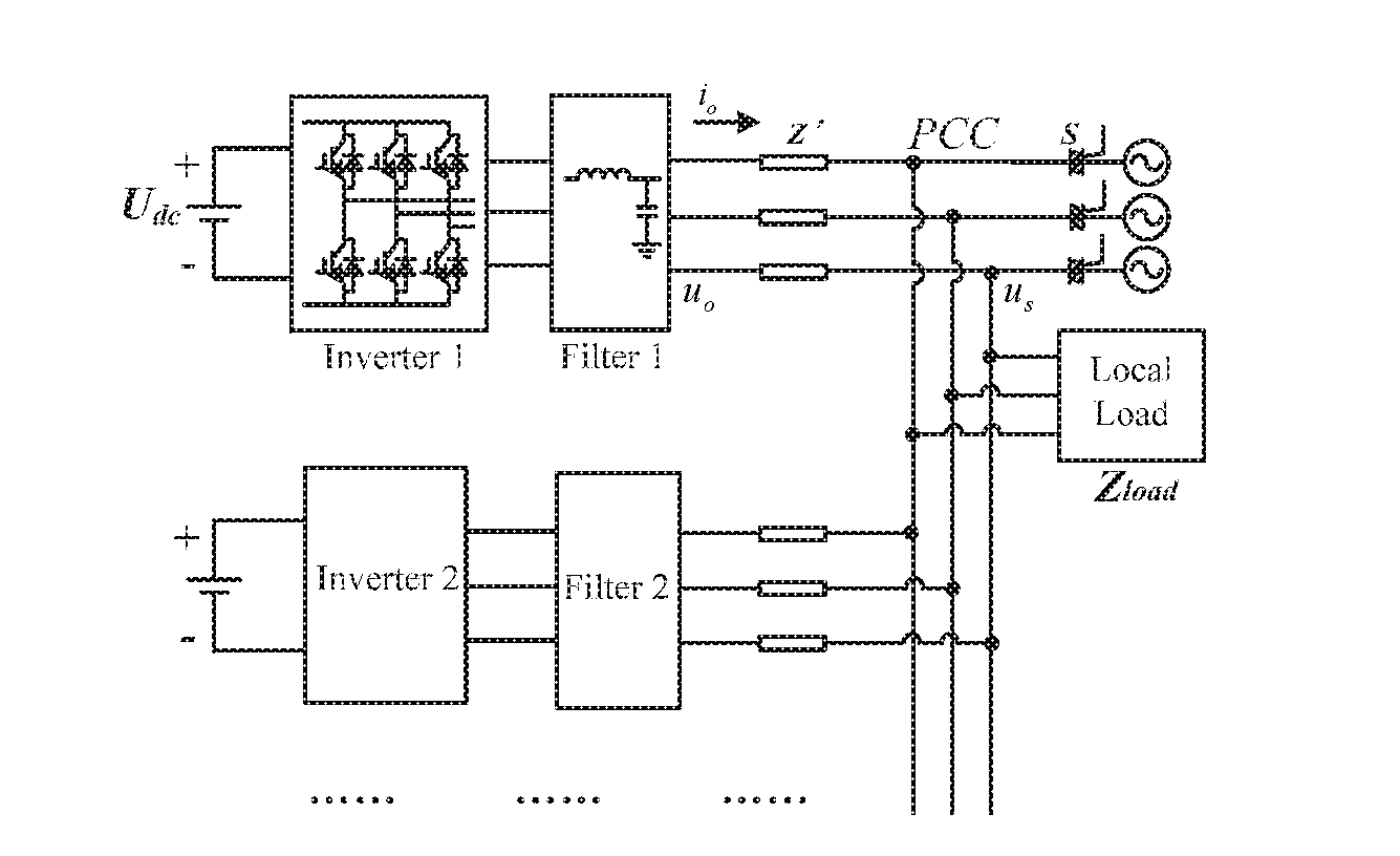
[0026]FIG. 1 is a schematic diagram of a micro-grid dual-mode inverter parallel structure in an embodiment of the present invention. The micro-grid dual-mode inverter parallel structure mainly includes a full-bridge inverter circuit, a filter, a local load, a grid-connected / off-grid switch, a grid, etc. A distributed power is converted into DC with a constant voltage, and the voltage is Udc; the DC is converted into AC by a three-phase PWM inverter circuit; the filter is used for filtering burrs caused by a high-frequency switch, and uo and io represent output voltage and current of the inverter after passing through the filter; the AC is output to provide electric energy to the local load Zload, and the grid-connected / off-grid switch S is used for connecting a micro-source with the grid. Wherein, the voltage of a point of common connection (PCC) is us, and the grid voltage mentioned in the present invention refers to the voltage at the PCC.

[0027]FIG. 2 is a block diagram of steady-...


PUM


Abstract

A steady state control method for a three-phase double-mode inverter. Off-grid steady state control is composed of outer loop power droop control, voltage feed-forward quasi-resonant control, and inner current loop dead-beat control. Therefore, the response speed of the inverter is raised, and the influence caused by the load fluctuation of a micro-grid is inhibited. Based on the off-grid steady state control, grid-connected steady state control introduces phase lead control to the power droop control. Therefore, the output voltage of the inverter is always slightly ahead of the power grid voltage, which avoids the energy pour backward phenomenon of the inverter due to a phase error, and realizes stable and reliable running in the grid-connected mode.

Description

FIELD OF THE INVENTION[0001]The present invention relates to the field of micro-grid distributed power generation, in particular to a steady-state control method of a three-phase dual-mode inverter.BACKGROUND OF THE INVENTION[0002]It is an effective way to solve the current energy crisis and environmental deterioration by micro-grid acceptance and using of distributed power (photovoltaic power, wind power, fuel cells and the like), where an inverter in the micro-grid is used as an interface of the distributed power and the micro-grid to convert distributed energy into high-quality electric energy, therefore researches on inverters which are suitable for the operation of the micro-grid is of great significance. The current researches mainly focus on control methods when the inverters work in a grid-connected mode or an off-grid (island) mode separately, but for inverters capable of working in the grid-connected and off-grid dual-mode, researches on corresponding smooth switch control...

Claims


Application Information

Patent Timeline
IPC IPC(8): H02M7/537H02M1/12
CPCH02M1/126H02M7/537H02M7/53871H02M7/5395H02M7/4815Y02B70/10H02J3/38H02J3/48
Inventor LUO, ANCHEN, YANDONGWANG, MINGYUEZHONG, QINGCHANGZHOU, LEMINGHUANG, YUANCHEN, ZHIYONGZHOU, XIAOPINGKUANG, HUIMINLI, MINGSHEN
Owner HUNAN UNIV
Why Eureka
Try Eureka