

Fishing Reel Drag Knob Assembly Capable of Showing Force
- Summary
- Abstract
- Description
- Claims
- Application Information
AI Technical Summary
Benefits of technology
Problems solved by technology
Method used
Image

Examples
Embodiment Construction
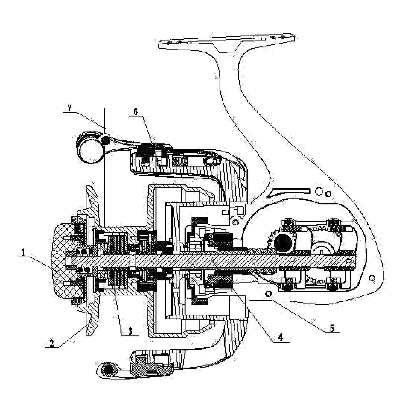
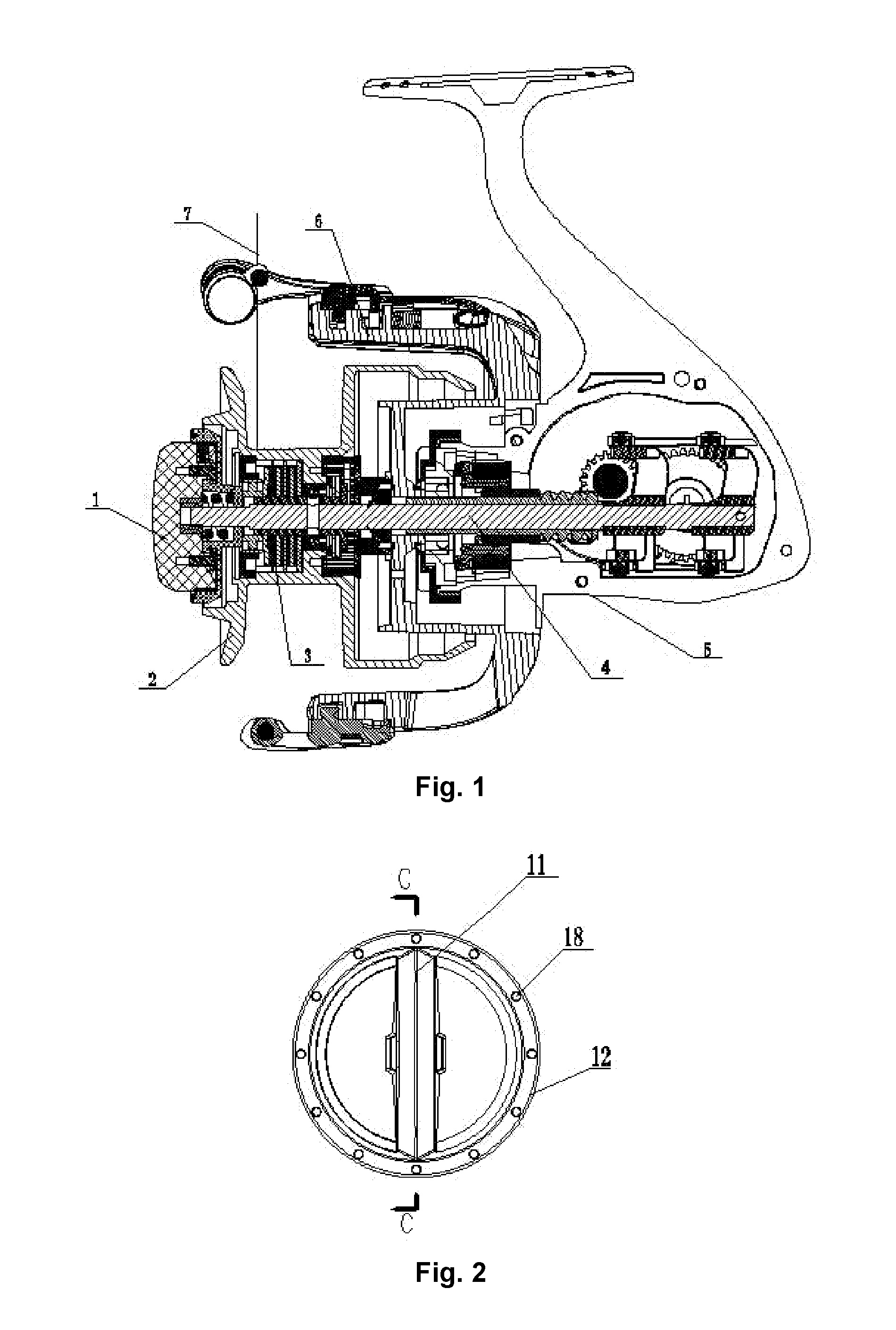
[0015]As shown in FIG. 1, a drag knob assembly 1 is installed on a main shaft 4 of a fishing reel, the main shaft 4 is configured to be moved back and forth under the drive of a machine body assembly 5, but to cannot rotate, and a line spool 2 is configured to be moved back and forth under the drive of the main shaft 4. The drag knob assembly 1 acts on a drag system 3 arranged between the line spool 2 and the main shaft 4 to adjust the rotation resistance of the line spool 2, so as to control the take-up and pay-off of a fishing line 7. During take-up, the pressure applied by the drag knob assembly 1 to the drag system 3 is enlarged, the rotation resistance of the line spool 2 is enlarged, the line spool 2 cannot rotate within a certain stress range, and a rotor 6 rotates to twist the fishing line 7 in a line slot of the line spool 2. During pay-off, the pressure applied by the drag knob assembly 1 to the drag system 3 is reduced, the rotation resistance of the line spool 2 is reduc...
PUM
 Abstract
Description
Claims
Application Information