
Printed Scaffold Structure for Hybrid Composites

a hybrid composite material and scaffold structure technology, applied in the direction of additive manufacturing, layered products, manufacturing tools, etc., can solve the problems of difficult support of hybrid composite materials during integration, and achieve the effect of allowing disassembly and reus

Active Publication Date: 2017-02-23
FLY DAVID E
View PDF1 Cites 0 Cited by
  • Summary
  • Abstract
  • Description
  • Claims
  • Application Information

AI Technical Summary

Benefits of technology

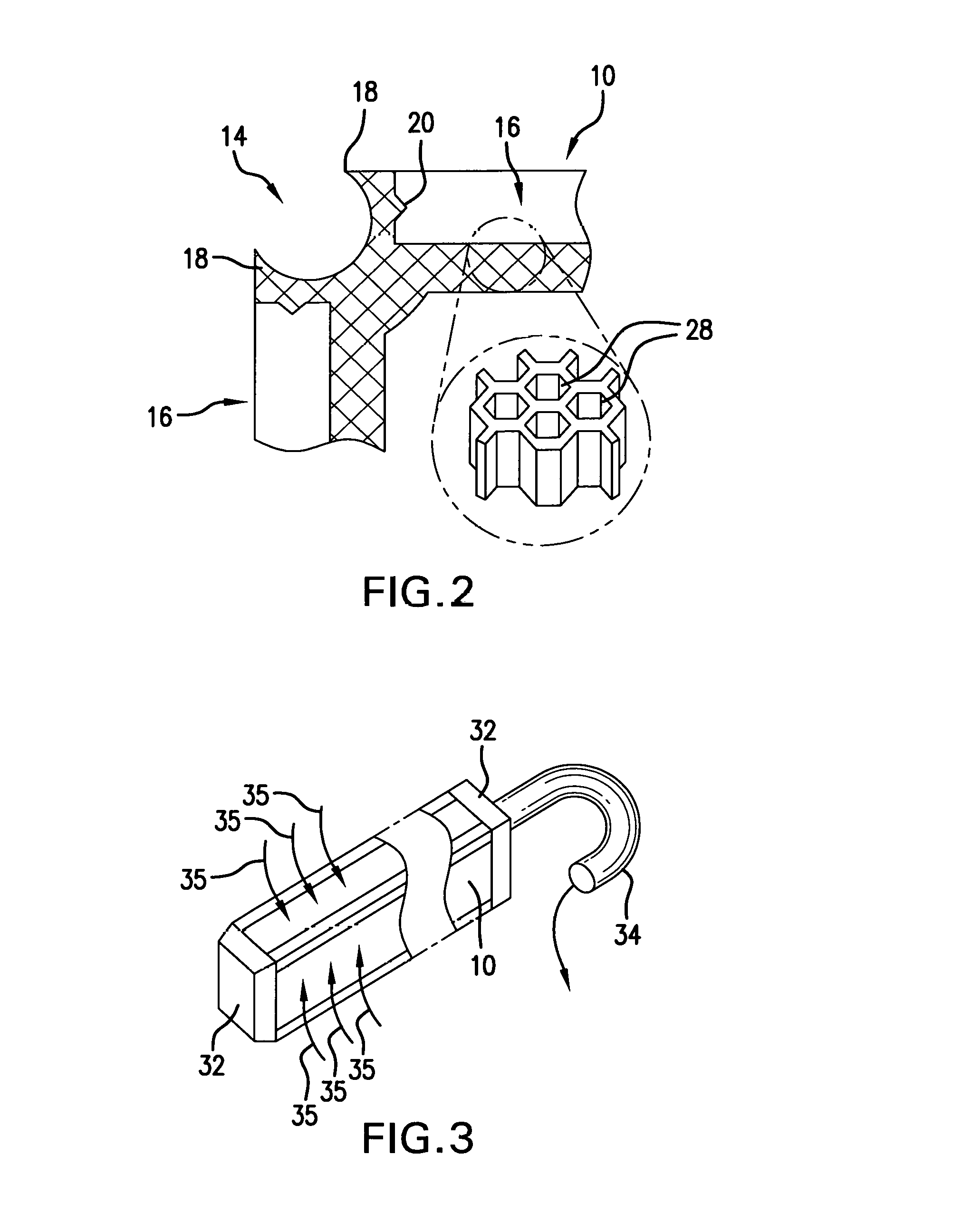
This patent describes a 3D printed scaffold that is designed to hold reinforcement components and support them when a secondary composite material is applied. The scaffold has retention features that can hold the components in different configurations, and it may be either sacrificial or reusable. The scaffold also has a microstructure that helps with the placement of the composite material. The printed scaffold acts as a guide or form for the woven fiber mat during assembly. Overall, this technology improves the efficiency and accuracy of the reinforcement process in composite manufacturing.

Problems solved by technology

Supporting the components of a hybrid composite material during integration can be difficult.

Method used


Image

  • Printed Scaffold Structure for Hybrid Composites
  • Printed Scaffold Structure for Hybrid Composites
  • Printed Scaffold Structure for Hybrid Composites

Examples


Embodiment Construction

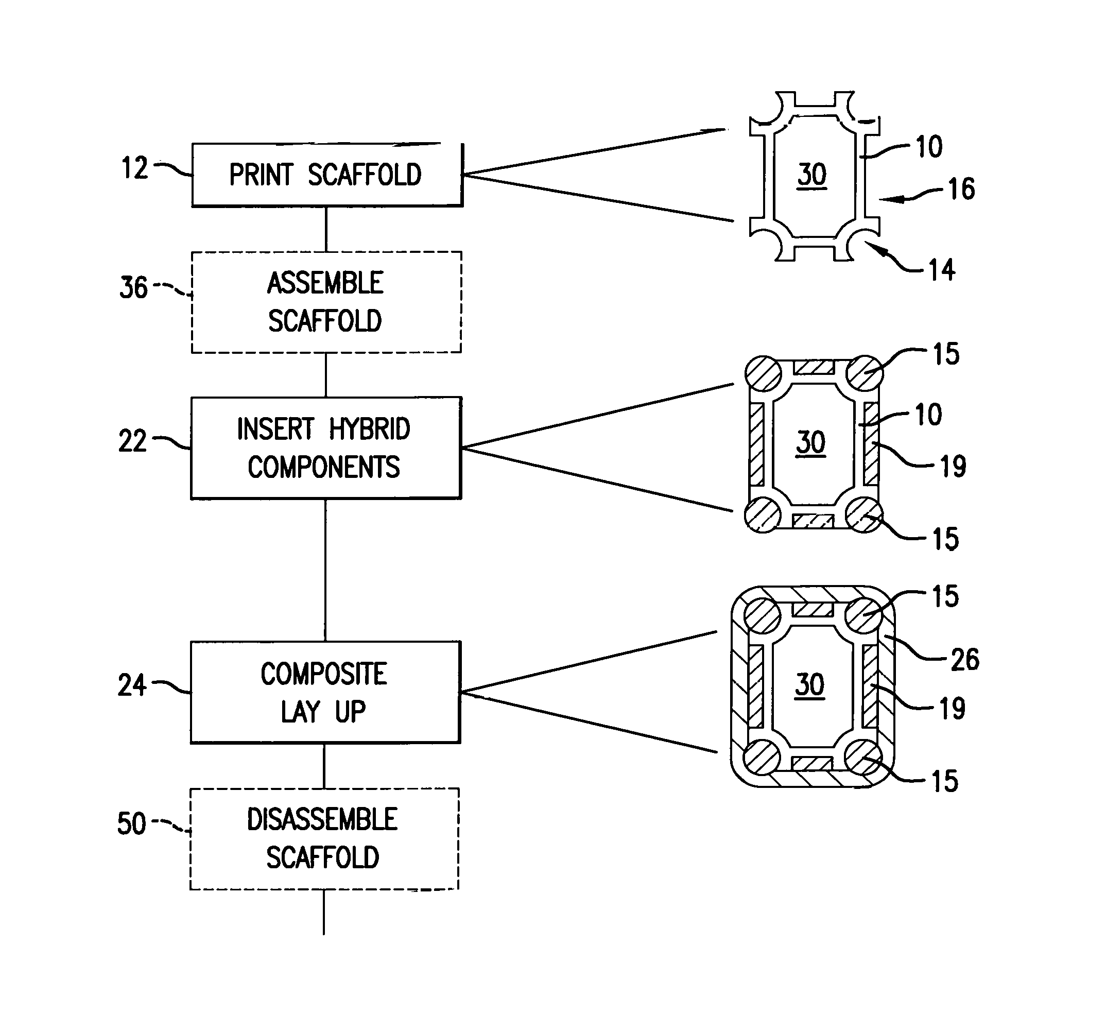
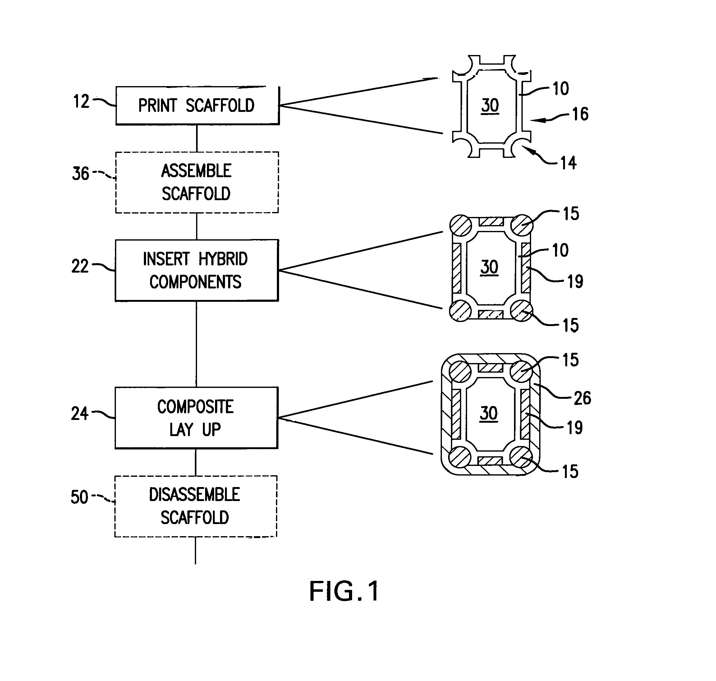
[0019]Referring now to FIG. 1, the present invention provides a manufacturing method in which a 3-D printed scaffold 10 is prepared, as indicated by process block 12, that will serve as a mold and retaining fixture in the construction of a hybrid composite material. The scaffold 10 may be printed by a variety of different 3-D printing technologies including, for example, those using extrusion processes such as the extrusion of a molten plastic filament (fused deposition modeling) and those using photo polymerization (stereolithography) or sintering (e.g., selective laser sintering) or the like. Importantly the material of the scaffold 10 may have relatively modest physical properties far beneath those required of the final hybrid composite product allowing a wide variety of materials to be used including, for example, low temperature or brittle polymers. The material of scaffold 10 may also have relatively stronger physical properties far above those of the hybrid composite polymers...


PUM

PropertyMeasurementUnit
heat conductingaaaaaaaaaa
strength propertiesaaaaaaaaaa
strengthaaaaaaaaaa

Abstract

The present invention provides a 3-D printed scaffold tailored to a particular hybrid composite material to receive the reinforcement components and support them during application of a secondary composite material. The printed scaffold may provide for retention features that locate and hold the reinforcement components in a variety of different configurations and may incorporate a microstructure having vacuum diffusion properties to assist in composite material lay-up. The invention contemplates either that the scaffold may be sacrificial (retained in hybrid composite) or constructed to permit disassembly and reuse. The 3D printed scaffold may also provide shapes or profile surfaces serving as layup forms that give shape to the woven fiber mat during assembly.

Description

CROSS REFERENCE TO RELATED APPLICATION[0001]This application claims the benefit of U.S. Provisional Application No. 62 / 206,609, filed Aug. 18, 2015.BACKGROUND OF THE INVENTION[0002]The present invention rotates to hybrid composite materials and in particular to a hybrid composite and a manufacturing process using a 3-D printed element in the fabrication of the hybrid composites.[0003]Hybrid composites are materials constructed from two different materials, one of which is a composite (for example, a fiber reinforced polymer with a metal, or two different fiber reinforced polymer matrices). The use of hybrid composites simplifies the design and manufacture of specialized materials by allowing pre-manufacture of one composite element having particular strength properties and then permitting the composite element to be assembled into a secondary composite to augment the strength of that secondary composite in a way that would be difficult to manufacture monolithically. For example, a r...

Claims


Application Information

Patent Timeline
Patent Type & Authority Applications(United States)
IPC IPC(8): B29C67/00B32B5/26B32B5/02B32B1/00B33Y10/00B33Y80/00
CPCB29C67/0092B33Y10/00B33Y80/00B32B5/024B32B2262/106B32B5/26B29K2307/04B32B2260/023B32B2260/046B32B1/00B29C64/40
Inventor FLY, DAVID E.
Owner FLY DAVID E
Learn More