Moisture sensor and steering system

a technology of moisture sensor and steering system, which is applied in the direction of secondary cells, batteries, instruments, etc., can solve the problem of power consumption of moisture sensor, and achieve the effect of reducing power consumption and consuming power

Active Publication Date: 2017-02-23
JTEKT CORP
View PDF1 Cites 14 Cited by
  • Summary
  • Abstract
  • Description
  • Claims
  • Application Information

AI Technical Summary

Benefits of technology

[0016]In this configuration, for example, even if one or both of the rack boots are broken to cause water to infiltrate into the housing, whether a signal is being output from the moisture sensor disposed inside the housing is determined t

Problems solved by technology

The moisture sensor consumes power only

Method used


Image

  • Moisture sensor and steering system
  • Moisture sensor and steering system
  • Moisture sensor and steering system

Examples


first embodiment

[0022]a steering system will be described below. The steering system in the present embodiment is what is called a rack-parallel electric power steering system (RP-EPS).

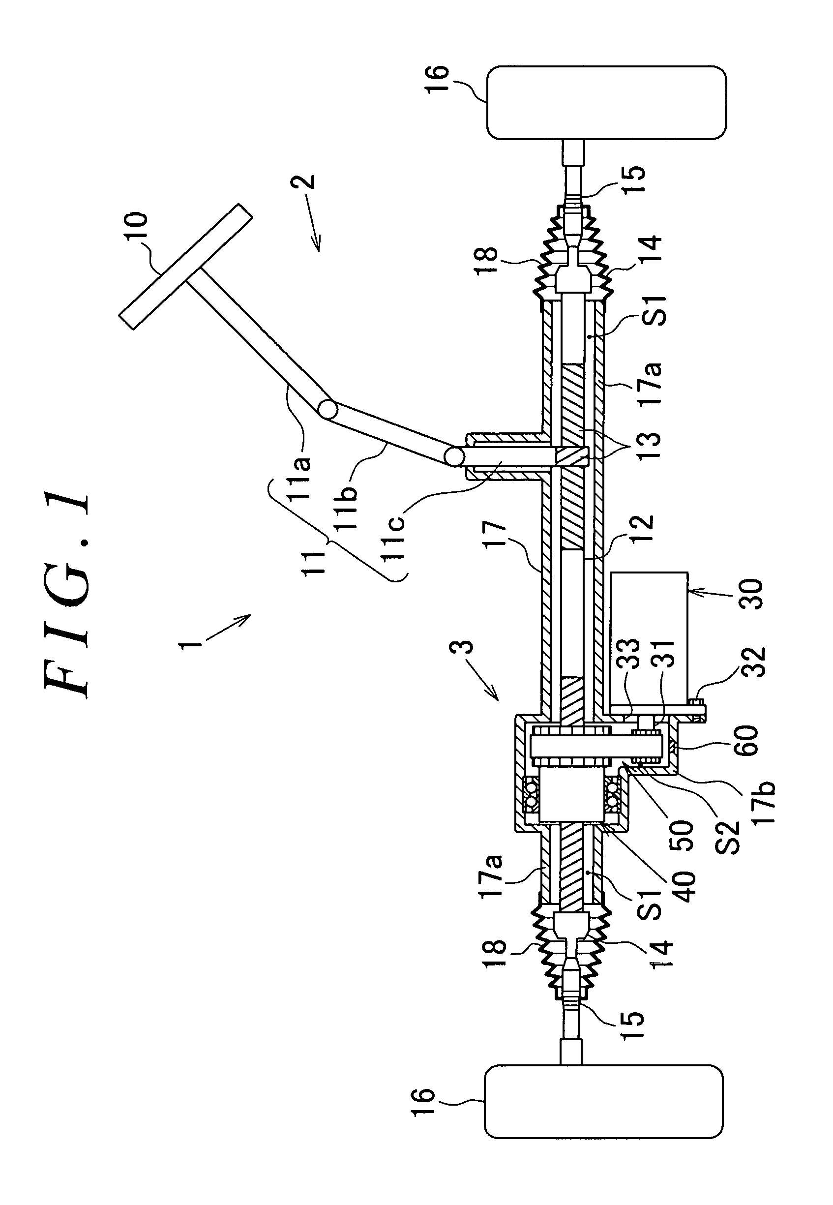
[0023]As depicted in FIG. 1, an EPS 1 includes a steering mechanism 2 that steers steered wheels 16 based on a driver's operation of a steering wheel 10 and an assist mechanism 3 that assists the driver's steering operation.

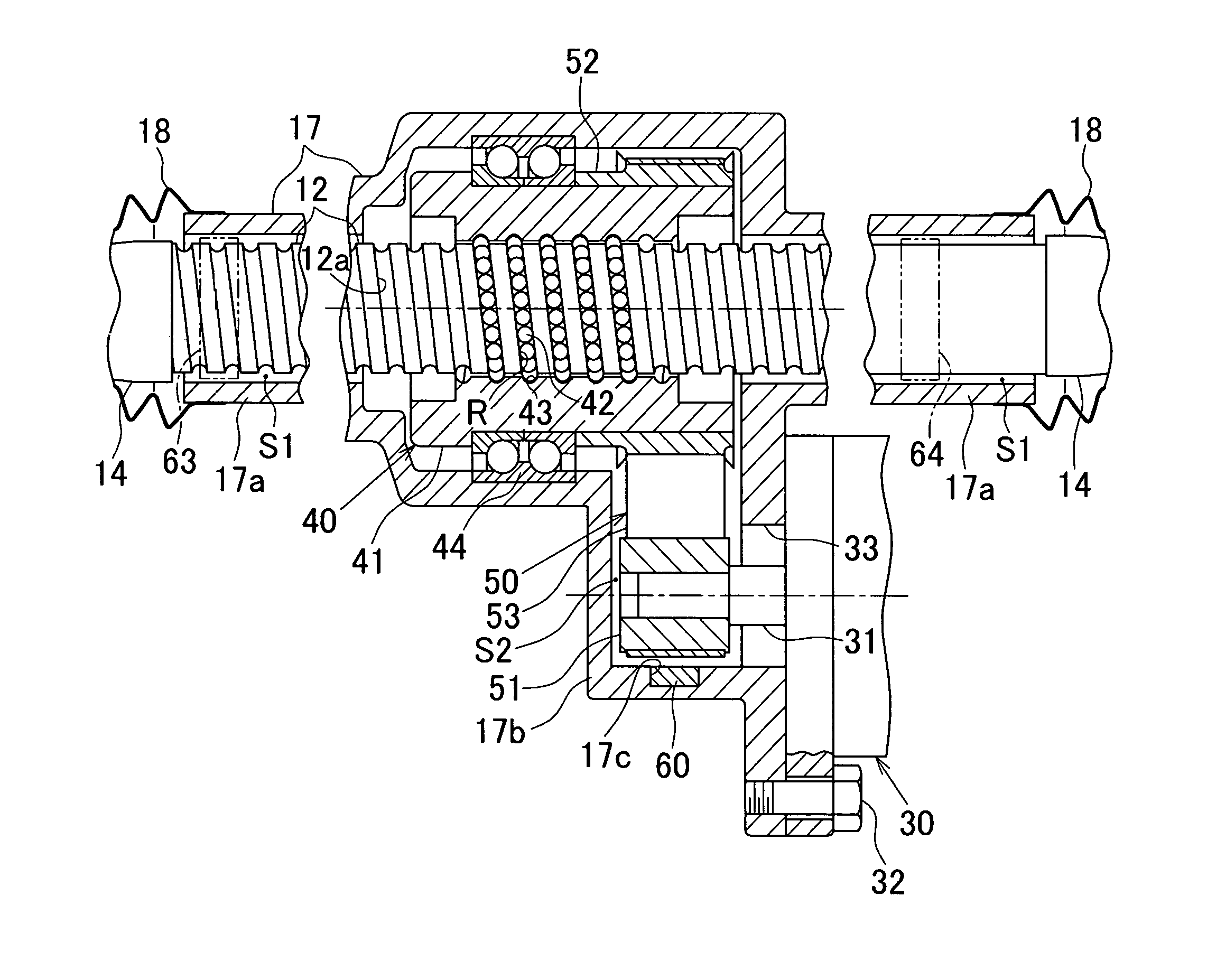
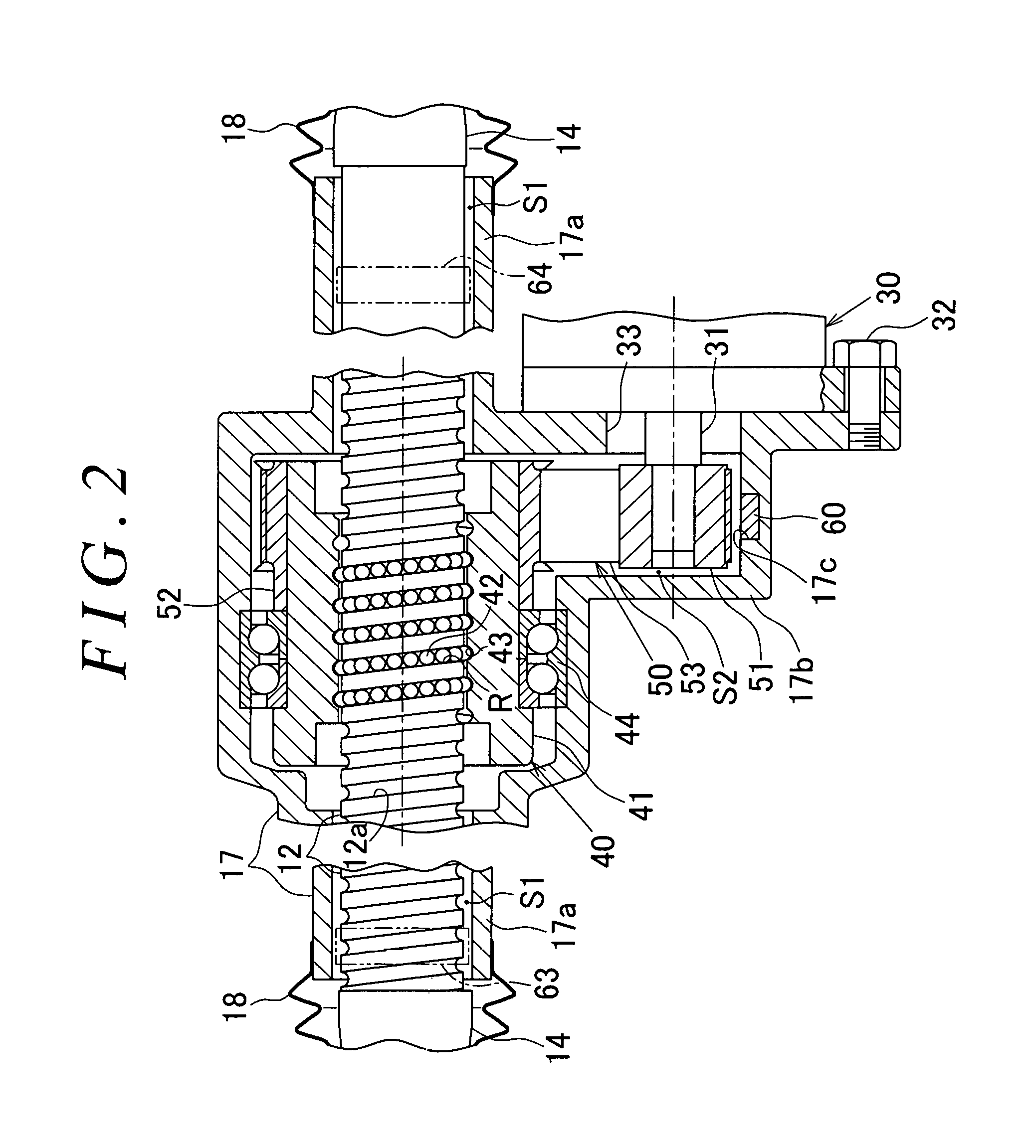
[0024]The steering mechanism 2 includes a steering wheel 10 and a steering shaft 11 that rotates integrally with the steering wheel 10. The steering shaft 11 has a column shaft 11a coupled to the steering wheel 10, an intermediate shaft 11b coupled to a lower end of the column shaft 11a, and a pinion shaft 11c coupled to a lower end of the intermediate shaft 11b. A lower end of the pinion shaft 11c is coupled to a rack shaft 12 via a rack-and-pinion mechanism 13. Therefore, the steering mechanism 2 converts rotary motion of the steering shaft 11 into reciprocating linear motion of the rack shaft 1...

second embodiment

[0055]In the second embodiment, the moisture sensors 63, 64 are provided at similar distances from the respective steered wheels 16 in the axial direction of the rack shaft 12. However, the invention is not limited to this. For example, the moisture sensor 63 may be provided at a longer distance from the corresponding steered wheel 16 than the moisture sensor 64. Even in this case, the control circuit 71 can estimate which of the rack boots is degraded when the moisture sensors 63, 64 are provided at different distances from the receiving circuit 73.

[0056]In the embodiments, the receiving circuit 73 in the air pressure monitoring system 70 is used as a receiving circuit that receives signals from the transmission circuit 62. However, the invention is not limited to this. For example, a receiving circuit dedicated to the transmission circuit 62 may be newly provided.

[0057]In the embodiments, the EPS 1 is provided with the air pressure monitoring system 70. However, the invention is n...


PUM


Abstract

A recessed portion is formed in an inner wall surface of a lower portion of a reduction gear housing (a lower wall in FIG. 2) in the direction of gravity and between a bearing 44 and an outer wall of the reduction gear housing (a right side wall in FIG. 2). The recessed portion is formed to have such a depth that the recessed portion does not penetrate the reduction gear housing. The recessed portion is formed in the reduction gear housing within a given range in a circumferential direction with respect to the axis of a rack shaft serving as the center. A moisture sensor is mounted in the recessed portion to detect water infiltrating into a housing. The moisture sensor has a transmission circuit that operates using a water battery as a power supply source. The water battery generates power when water flows into the water battery.

Description

INCORPORATION BY REFERENCE[0001]The disclosure of Japanese Patent Application No. 2015-163970 filed on Aug. 21, 2015 including the specification, drawings and abstract, is incorporated herein by reference in its entirety.BACKGROUND OF THE INVENTION[0002]1. Field of the Invention[0003]The invention relates to a moisture sensor and a steering system.[0004]2. Description of the Related Art[0005]Steering systems have been available which vary the angle of steered wheels by transmitting rotation of a steering shaft resulting from steering of a steering wheel to a rack-and-pinion mechanism as described in, for example, Japanese Patent Application Publication No. 2014-234102 (JP 2014-234102 A). The rack-and-pinion mechanism converts rotary motion of the steering shaft into linear motion of a rack shaft. The rack shaft and the rack-and-pinion mechanism are housed in a housing. Tie rods are coupled to respective opposite ends of the rack shaft via rack ends so as to be able to pivot. The lin...

Claims


Application Information

Patent Timeline
IPC IPC(8): B62D5/04G01N27/12H01M10/42B62D5/00H01M10/48
CPCB62D5/0481B62D5/008B62D5/0445H01M2010/4278H01M10/425G01N27/121H01M2220/20H01M10/48B62D5/04B62D5/0403B62D5/0448H01M6/34
Inventor ASAKURA, TOSHIHIROOGAWA, KEISUKETOYODA, HIROYUKI
Owner JTEKT CORP
Why Eureka
Try Eureka