Light emitting diode lamps and related methods

a technology of light-emitting diodes and led light sources, which is applied in the direction of lighting device details, light sources, lighting and heating apparatus, etc., can solve the problems of reduced light-emitting intensity and service life of led light sources, inefficient led lamps, and heat buildup, so as to achieve rapid replacement, efficient heat dissipation, and rapid replacement of driver circuits

Active Publication Date: 2017-02-23
AURORALIGHT INC
View PDF1 Cites 4 Cited by
  • Summary
  • Abstract
  • Description
  • Claims
  • Application Information

AI Technical Summary

Benefits of technology

[0015]It is an objective of this disclosure to describe an LED lighting module (including but not limited to lamps, light bulbs, or light fixtures) with (i) rapidly replaceable LED light source units, (ii) rapidly replaceable driver circuitry, and (iii) efficient heat dissipation. An aspect of the rapid replaceability of the disclosed light source is self-registration of the source's light elements, electronic drive components, and heat sources respectively relative to the optical, power leads or pins, and heat sink components of a lamp or other lighting device. It is yet another object of the present application to meet the aforementioned needs without any of the drawbacks associated with apparatus heretofore known for the same purpose. It is yet still a further objective to meet these needs in an efficient and inexpensive manner.

Problems solved by technology

Although better than alternative light sources, LED lamps can be inefficient, where in some cases, 80% to 85% of input power is converted to heat rather than light.
This inefficiency can result in heat buildup and, if the heat is not dissipated effectively, light emitting intensity and service life of the LED light source are reduced significantly.
place. Such traditional LED bulbs are tedious to assemble because, among other reasons, (a) the wiring 15 must be soldered or otherwise connected to the driver and pins 13 and LED light source(s) 14; the PCB 16 must be screwed into the base and housing via a screw driver; and, usually a spanner wrench and other special purpose tools must be had for dismantling and reassembling an LE
Such traditional LED bulbs are tedious to assemble because, among other reasons, the wiring 15 must be soldered or otherwise connected to the driver and pins 13 and LED light source 14.
Traditional LED lamps, like the MR-16 lamp, have also not adequately addressed the heat-dissipation problems associated with LED light sources.
For instance, heat cannot be effectively dissipated from the LED light source in a traditional bulb because the LED is positioned on insulation or a PCB.
Likewise, when failure of driver circuitry or driver components occurs, these are equally difficult and impractical to replace.
All of these problems render such MR-16 bulbs unserviceable.
Although an improvement to traditional LED lamps, the lamp disclosed by Yu et al. has various limitations.
For instance, the threading of a small LED light source into an equally small adapter can be tedious and requires tools.
's lamp requires exact tolerances or else the assembly cannot be constructed.
Additionally, when a driver component or components fail, replacement is difficult since the driver 24 is glued into the housing 21 and may also require unsoldering and re-soldering of wires to effect such replacement.
's LED lamp accomplishes heat transfer to the ambient environment via the conduction of heat through the interface of several components of the lamp, which is less efficient than conductive heat transfer through the interface of two or less components of the lamp.

Method used


Image

  • Light emitting diode lamps and related methods
  • Light emitting diode lamps and related methods
  • Light emitting diode lamps and related methods

Examples


Embodiment Construction

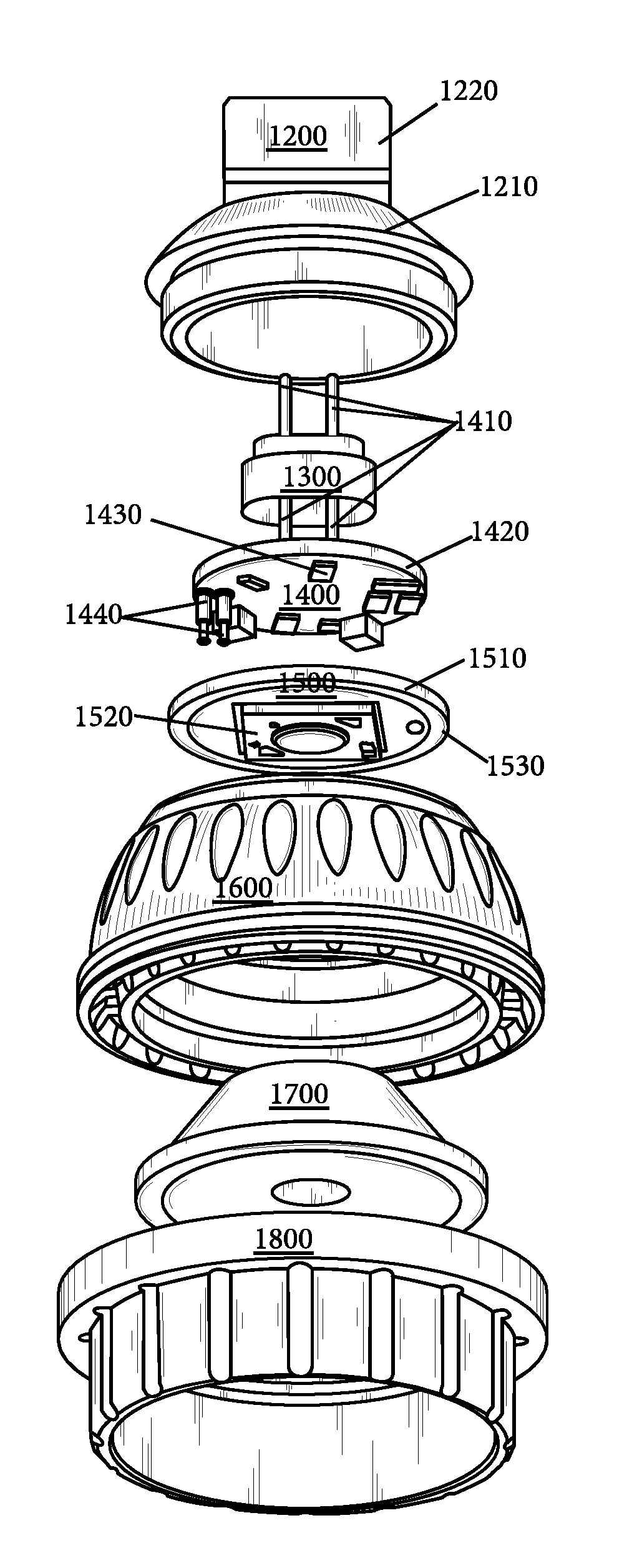
[0049]Generally disclosed is an LED lighting module (including but not limited to lamps, light bulbs, or light fixtures) with (i) rapidly replaceable LED light source units and (ii) rapidly replaceable driver circuitry, and (iii) efficient heat transfer. An aspect of the rapid replaceability of the disclosed lighting device is self-registration of the device's heat sources (e.g., light elements, electronic drive components) relative to the optical, power leads or pins, and finally, heat sink components of the lighting device. Preferably, self-registration may be accomplished via at least one of (a) corresponding geometries between the various components of the LED lighting device, (b) power transmission regions, areas or zones on the LED lighting module that interface with power leads or pins of the lamp or lighting device, or (c) thermal conduction regions, areas or zones that interface with heat dissipation elements of the lamp or lighting device. In a preferred embodiment, the mo...


PUM


Abstract

Generally disclosed may be an LED lighting module (including but not limited to lamps, light bulbs, or light fixtures) with (i) rapidly replaceable LED light source units, (ii) rapidly replaceable driver circuitry, and (iii) efficient heat transfer. An aspect of the rapid replaceability of the disclosed light source is self-registration of the source's light elements, electronic drive components, and heat sources respectively relative to the optical, power supply components, and heat sink components of a lamp or other lighting device.

Description

CROSS-REFERENCE TO RELATED APPLICATIONS[0001]This application claims the benefit and priority of U.S. Prov. App. Ser. No. 62 / 207,303 (filed Aug. 19, 2015) by Michael Joye entitled “Light emitting diode lamps and related methods.”STATEMENT REGARDING FEDERALLY SPONSORED RESEARCH OR DEVELOPMENT[0002]Not applicable.THE NAMES OF THE PARTIES TO A JOINT RESEARCH AGREEMENT[0003]Not applicable.REFERENCE TO AN APPENDIX SUBMITED ON A COMPACT DISC AND AN INCORPORATED BY REFERENCE OF THE MATERIAL ON THE COMPACT DISC[0004]Not applicable.STATEMENT REGARDING PRIOR DISCLOSURES BY THE INVENTOR OR A JOINT INVENTOR[0005]Reserved for a later date, if necessary.BACKGROUND OF THE INVENTION[0006]Field of Invention[0007]The present application is in the field of light emitting diode (LED) lamps and related methods.[0008]Background of the Invention[0009]An LED is a two-lead semiconductor light source. LEDs have become widespread for use in lighting applications because LEDs are favorably smaller in size, low...

Claims


Application Information

Patent Timeline
Patent Type & Authority Applications(United States)
IPC IPC(8): F21K9/238F21K9/23F21V23/00F21V23/02F21V29/70
CPCF21K9/238F21V23/02F21Y2115/10F21V23/006F21K9/23F21V29/70F21V23/06
Inventor JOYE, MICHAELHRADNANSKY, JOHN JAMES
Owner AURORALIGHT INC
Why Eureka
Try Eureka