Swirler for a burner of a gas turbine engine, burner of a gas turbine engine and gas turbine engine

a gas turbine engine and burner technology, applied in the direction of burners, combustion types, combustion processes, etc., can solve the problems of unstable flames and high risk of burning, and achieve the effect of easy and cost-effective, high-efficiency carbon build-up

Inactive Publication Date: 2017-02-23
SIEMENS AG
View PDF4 Cites 3 Cited by
  • Summary
  • Abstract
  • Description
  • Claims
  • Application Information

AI Technical Summary

Benefits of technology

[0011]It is an object of the present invention to solve the aforesaid problems and drawbacks at least partly. In particular, it is an object of the present invention to provide a swirler, a burner and a gas turbine engine, which allow an injection of especially liquid pilot fuel in an easy and cost efficient way with no or at least highly reduced carbon build up on surfaces of the swirler and / or the burner and / or the combustion can of the gas turbine engine.

Problems solved by technology

Therefore the flame can be unstable and likely to go out.

Method used


Image

  • Swirler for a burner of a gas turbine engine, burner of a gas turbine engine and gas turbine engine
  • Swirler for a burner of a gas turbine engine, burner of a gas turbine engine and gas turbine engine
  • Swirler for a burner of a gas turbine engine, burner of a gas turbine engine and gas turbine engine

Examples


second embodiment

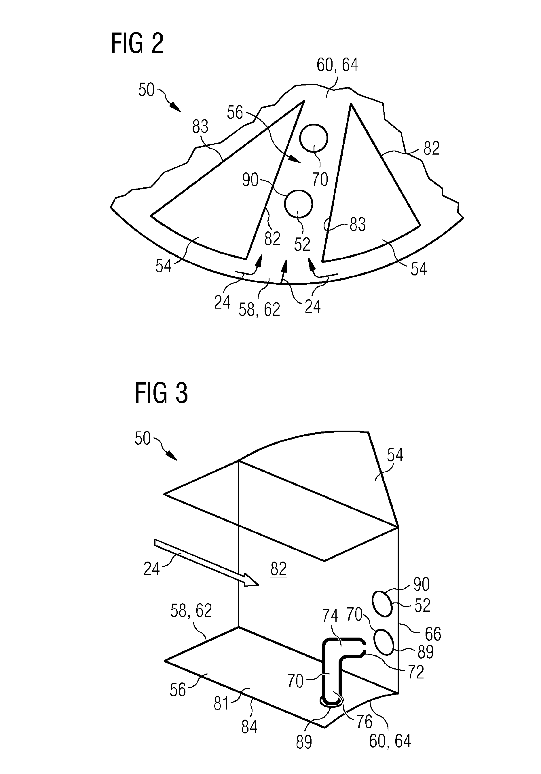
[0037]FIG. 3 shows a side view of a part of a swirler 50 according to the invention. A single vane 54 and the adjacent mixing channel 56 are shown. An arrow symbolizes the air 24 channelled through the mixing channel 56 from its outer end 58 located essentially at the outer radius 62 of the swirler 50 to its inner end 60 located essentially at the inner radius 64 of the swirler 50. Several possible embodiments of a pilot injection means 70 are depicted. One of the pilot injection means 70 is constructed as a fuel injection lance 76. Such a fuel injection lance 76 can advantageously be constructed as a removable fuel injection lance 76. A replacement of the pilot injection means 70 is in this case possible in a very easy manner, especially if the fuel injection lance 76 can be removed from outside of the assembly of the swirler 50.

[0038]Further, the fuel injection lance 76 shown in this figure comprises an angled tip 74. At the end of the angled tip 74 an injection point 72 of this p...

third embodiment

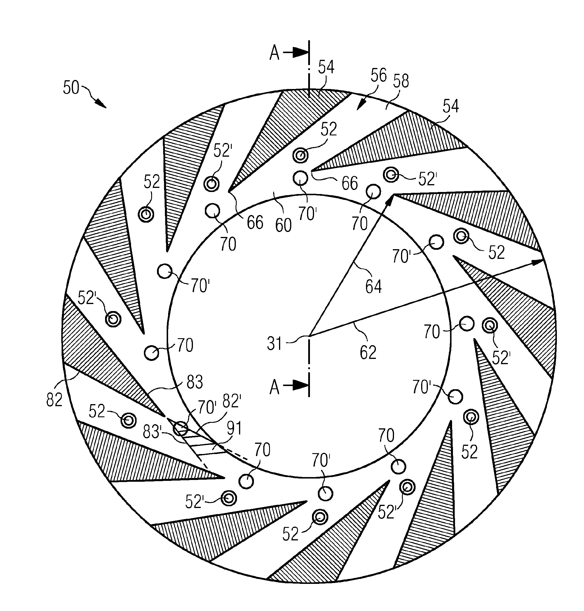
[0039]In FIG. 4 a sectional view of a swirler 50 according to the invention is depicted. The swirler 50 comprises a plurality of vanes 54 extending from an outer radius 64 to an inner radius 62, only two of them marked with reference signs for lucidity. Between the vanes 54 a plurality of mixing channels 56 is located, of which only one is marked with a reference sign for lucidity. The mixing channels extend from an outer end 58 to an inner end 60. In this embodiment of a swirler 50 according to the invention, in each of the mixing channels 56 a main injection means 52 is positioned, each at a slightly different radial position. This contains the advantage that for different operation modes of the gas turbine engine 10 (not shown), for instance different load levels, a special set of main injection means 52, adjusted for instance in total number and / or pattern, can be used.

[0040]Further, at the inner end 60 of each of the mixing channels 56 and near a trailing edge 66 of the vanes 5...


PUM


Abstract

A swirler for a burner of a gas turbine engine, having a plurality of vanes extending from an outer radius of the swirler to an inner radius of the swirler and a plurality of mixing channels between the vanes to channel air from a radially outer end of the mixing channel, located essentially at an outer radius of the swirler, to a radially inner end of the mixing channel, located essentially at an inner radius of the swirler, at least one main injector for providing fuel for a main flame of the gas turbine engine, the main injector arranged at and/or in at least one of the mixing channels, and at least one pilot injector for providing fuel for a pilot flame of the gas turbine engine. A burner of a gas turbine engine and a gas turbine engine include the swirler.

Description

CROSS REFERENCE TO RELATED APPLICATIONS[0001]This application is the US National Stage of International Application No. PCT / EP2015 / 060127 filed May 7, 2015, and claims the benefit thereof. The International Application claims the benefit of European Application No. EP14167655 filed May 9, 2014. All of the applications are incorporated by reference herein in their entirety.FIELD OF INVENTION[0002]The present invention is related to a swirler for a burner of a gas turbine engine, comprising a plurality of vanes extending from an outer radius of the swirler to an inner radius of the swirler and a plurality of mixing channels between the vanes to channel air from a radially outer end of the mixing channel, located essentially at an outer radius of the swirler, to a radially inner end of the mixing channel, located essentially at an inner radius of the swirler, at least one main injection means for providing fuel for a main flame of the gas turbine engine, the main injection means arrang...

Claims


Application Information

Patent Timeline
Patent Type & Authority Applications(United States)
IPC IPC(8): F23R3/14F23R3/34F23R3/28
CPCF23R3/14F23R3/343F23R3/286F23R3/38F23C7/002F23D14/24
Inventor DOLMANSLEY, TIMOTHY
Owner SIEMENS AG
Why Eureka
Try Eureka