Light shield using integrated lighting to create opacity and privacy in windows

a technology of integrated lighting and windows, applied in the field of windows, can solve the problems of relative high cost of windows, difficulty in selecting intermediate levels of privacy, and suffering from the same problems, and achieve the effect of saving energy and increasing the radiation intensity of the lighting uni

a technology of integrated lighting and windows, applied in the field of windows, can solve the problems of relative high cost of windows, difficulty in selecting intermediate levels of privacy, and suffering from the same problems, and achieve the effect of saving energy and increasing the radiation intensity of the lighting uni

US20170052289A1Inactive Publication Date: 2017-02-23SIGNIFY HLDG BV

Image

  • Light shield using integrated lighting to create opacity and privacy in windows
  • Light shield using integrated lighting to create opacity and privacy in windows
  • Light shield using integrated lighting to create opacity and privacy in windows

Examples


Embodiment Construction

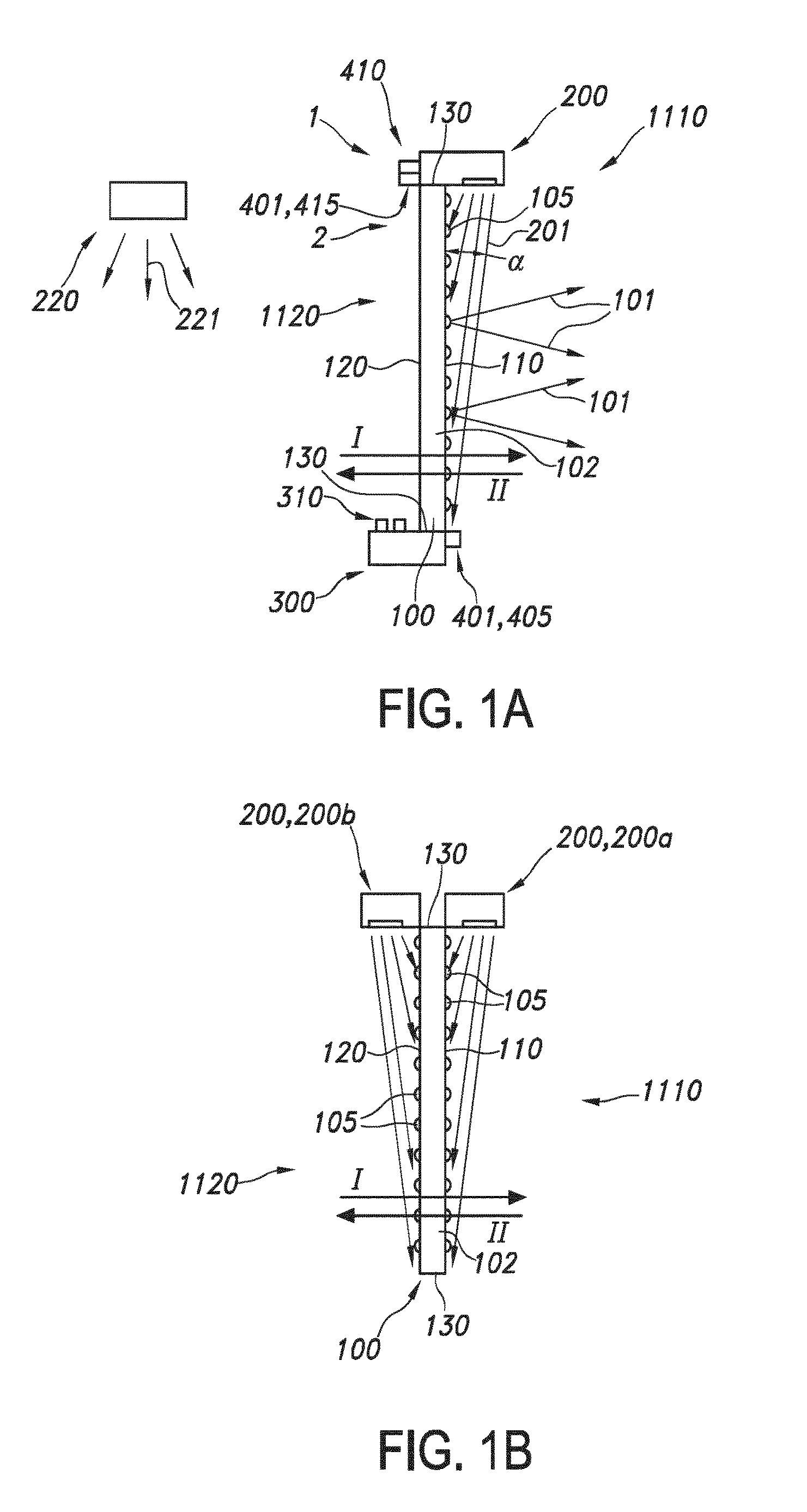
[0066]FIG. 1a schematically depicts an embodiment of a privacy window system 1 comprising a window panel 100, a control unit 300, and a lighting unit 200 comprising at least one light source (not shown) for generation of lighting unit radiation (201) during operation.

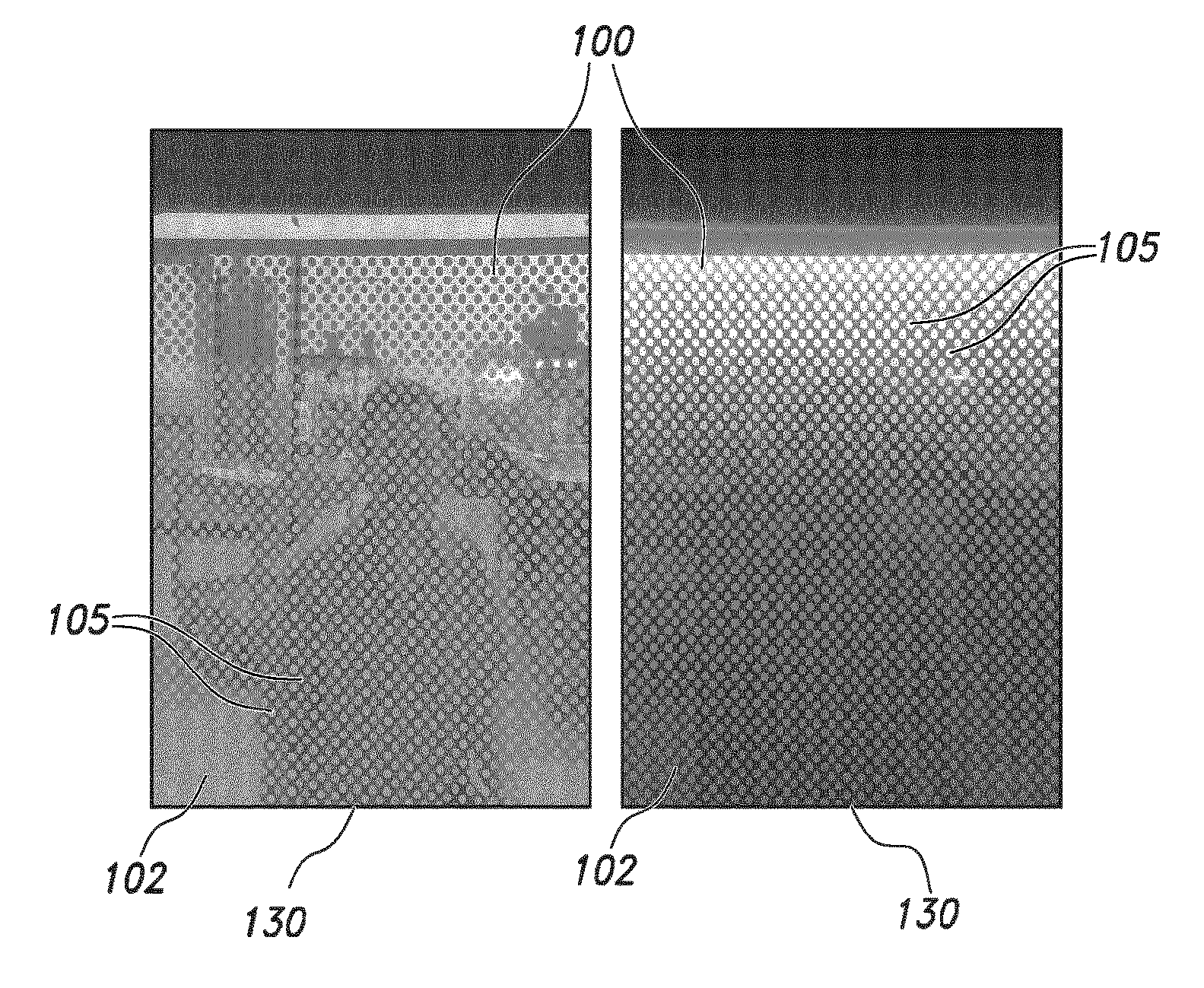
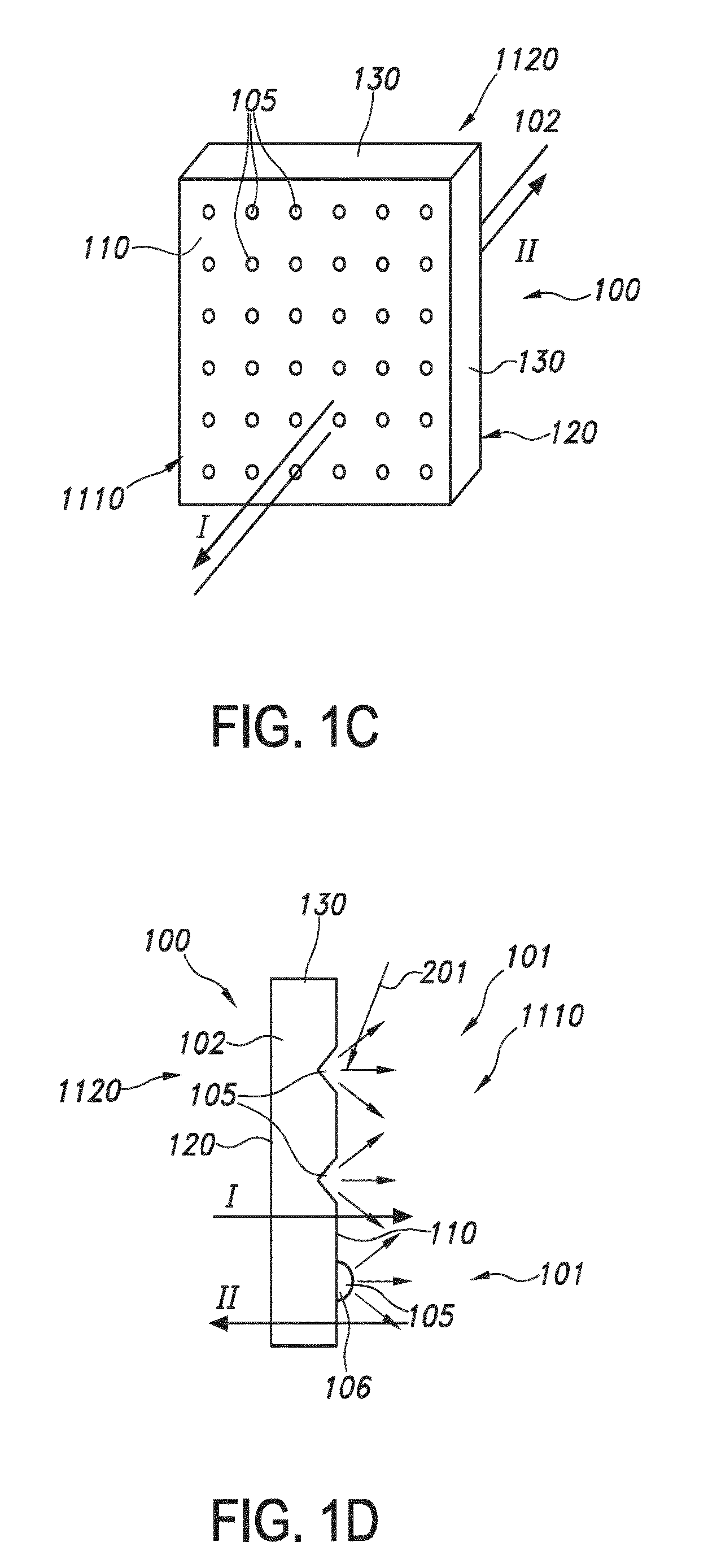
[0067]The window panel 100 comprises a first surface 110, a second surface 120 and an edge 130. The invention is especially not based on the use of edge lighting. Especially, there is no edge lighting at all. The window panel defines also two sides, a first side 1110, which is in herein only for the sake of understanding associated with the first surface 110, i.e. the first side 1110 is that space in direction I starting from the first side 1110, and a second side 1120 (opposite of the first side, relative to the window panel 100), which is in herein only for the sake of understanding associated with the second surface 120, i.e. the second side 1120 is that space in direction II starting from the second side 1120.

[0068]...


PUM


Abstract

The invention provides a privacy window system (1) comprising a window panel (100), a lighting unit (200), and a control unit (300), wherein (i) the window panel (100) comprises a first surface (110), a second surface (120) and an edge (130), wherein the window panel (100) is transmissive for visible light wherein at least one of the surfaces (110,120) of the window panel (100) comprises surface structures (105), configured to generate visible privacy light (101) under irradiation with lighting unit radiation (201); (ii) instead of using edge-lighting for the irradiation of the window panel (100), the lighting unit (200) is configured to irradiate one of the surfaces (110,120) of the window panel (100) with said lighting unit radiation (201) thereby inducing said privacy light (101) and reducing visibility through the window panel (100) in at least one direction; and (iii) the control unit (300) is configured to control the lighting unit radiation (201) as function of an input signal.

Description

FIELD OF THE INVENTION[0001]The invention relates to a window system as well as to the use thereof.BACKGROUND OF THE INVENTION[0002]Privacy windows are known in the art. WO2006 / 081186, for instance, describes in an embodiment a lighted privacy window which may comprise an at least partially transparent panel within a divider. The panel may be constructed in a manner such that when the lighted privacy window is in an “on-state,” the panel is illuminated from within with light generated by one or more LED-based lighting units integrated in some manner with the panel, thereby becoming opaque and affording increased privacy. In one aspect, significant opacity results from reflections of the illumination within the panel due to perturbations in or on the surface of the panel that serve as scattering centers for the generated light. For example, a surface of the panel may be laminated or physically agitated (e.g., via sandblasting, etching, acid, laser beam, applied frit, etc.) in order t...

Claims


Application Information

Patent Timeline
23 Feb 2017
Publication
US20170052289A1
IPC
G02B5/02; H05B37/02
CPC
G02B5/0284; H05B37/0227; H05B37/0218; G02B5/0226; F21V33/0016; F21V23/0464; E06B3/00; E06B3/6715
Inventors
BOISSEVAIN, CHRISTOPHER JAMES; SCHOBBEN, DANIEL WILLEM ELISABETH