
Eureka
For R&D, Eureka makes reading and utilizing patents & technical documents easy.
Eureka AIR
Designed for self-driven R&D workflows. Generate viable solutions, solve complex R&D challenges, empower your innovation with AI.

Eureka Materials
Designed for material experts only. Revolutionize your material R&D, from search, analyze, to developing new materials.

TechResearch
Generate reliable direction feasibility study reports for your R&D in just a few steps.

TechSeek
Discover and master advanced knowledge NOW. Basics, ideas, possibilities, all at once.

TechMind
As an expert in R&D Theories, TechMind can generates customized viable solutions instantly.

TechRisk
Analyze your overall solution with one click, know your potential R&D risks in advance.

TechMonitor
Get weekly tech updates, stay abreast of the latest tech innovations and key insights.
Terminal apparatus, base station, and program
- Summary
- Abstract
- Description
- Claims
- Application Information
AI Technical Summary
Benefits of technology
Problems solved by technology
Method used
Image

Examples
first embodiment
3. First Embodiment
3-1. Configuration Example of Base Station
[0093]Firstly, a configuration of the base station 100 according to this embodiment will be described with reference to FIG. 7 to FIG. 14.
[0094]FIG. 7 is a block diagram showing an example of a logical configuration of the base station 100 according to this embodiment. As shown in FIG. 7, the base station 100 includes an antenna unit 110, a wireless communication unit 120, a storage unit 130, and a control unit 140.
(Antenna Unit 110)
[0095]The antenna unit 110 radiates a signal output by the wireless communication unit 120, in the form of radio waves, into space. The antenna unit 110 also converts radio waves in space into a signal, and outputs the signal to the wireless communication unit 120.
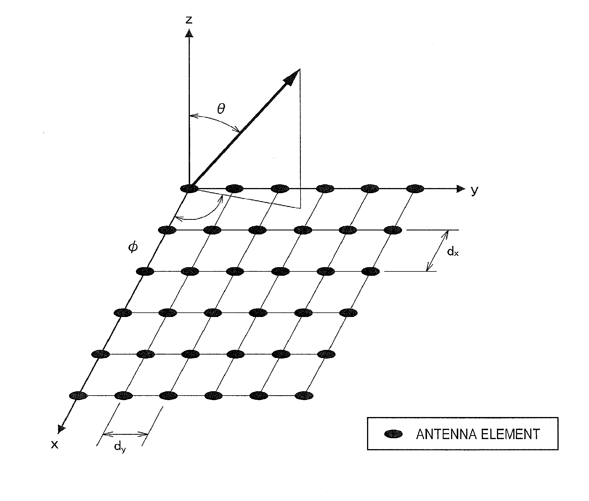
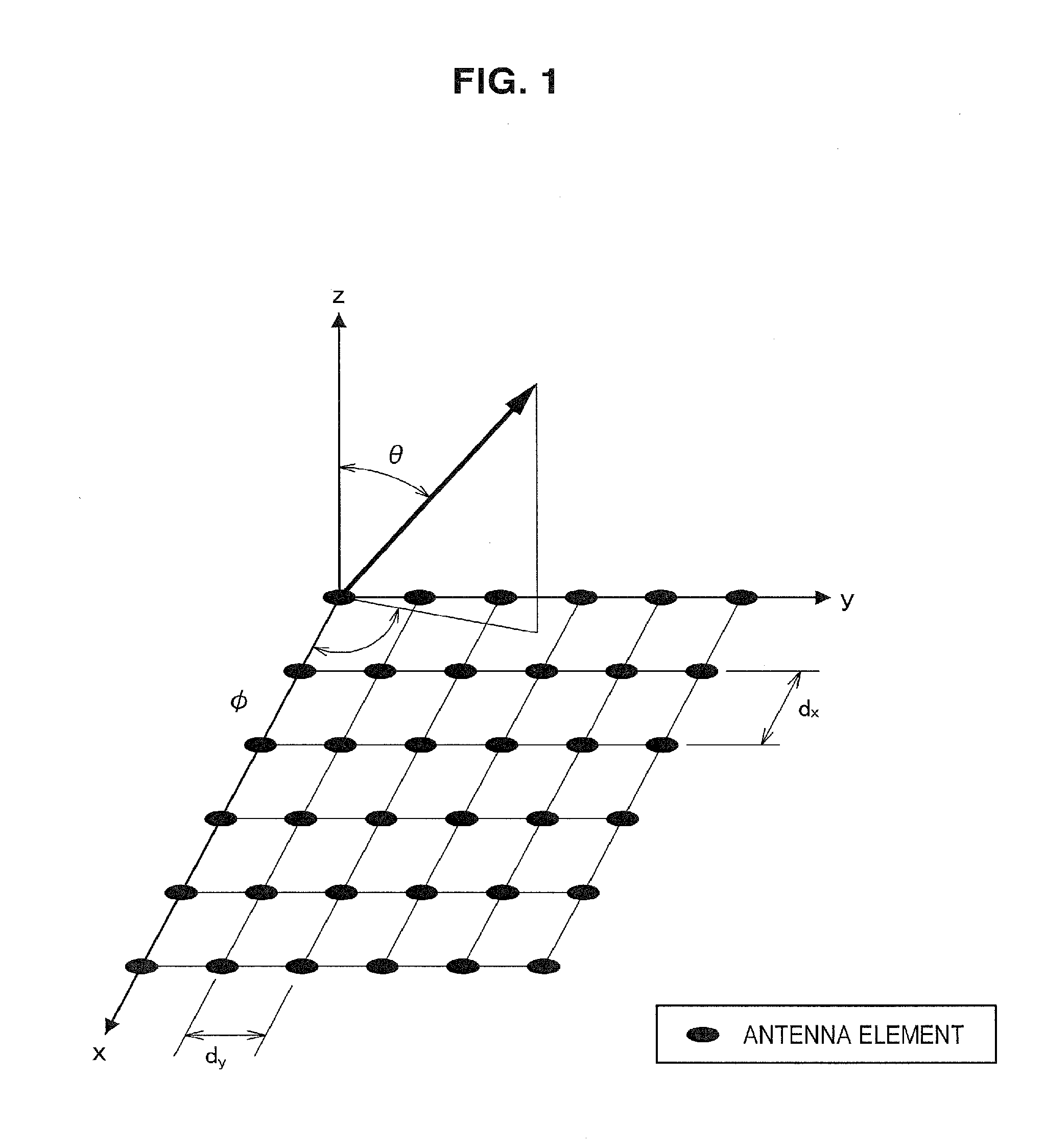
[0096]In particular, in an embodiment of the present disclosure, the antenna unit 110 includes a directional antenna. For example, the directional antenna is a directional antenna which can be used in large-scale MIMO.
[0097]Also, for ...
second embodiment
4. Second Embodiment
4-1. Overview
[0190]In the first embodiment, a measurement reference signal to which a candidate set for a weight set has been applied is used instead of a CRS. Therefore, in a terminal apparatus 200, a spatial channel H multiplied by a candidate set for a weight set is measured instead of the original spatial channel H. Therefore, in the first embodiment, it is difficult to perform operation which requires the original spatial channel H.
[0191]For example, in the communication system 1 according to the first embodiment, it is difficult to use Transmission Modes 4, 5, and 6 of LTE, which are defined in the 3GPP. In these operation modes, a spatial channel H multiplied by one weight set is compared with the spatial channel H multiplied by another weight set, whereby evaluation is performed for each weight set. A spatial channel H multiplied by a candidate set for a weight set, which is measured in the first embodiment, is difficult to do such evaluation.
[0192]Theref...
third embodiment
5. Third Embodiment
5-1. Configuration Example of Base Station
[0221]A base station 100 has a configuration similar to that of the first embodiment. Note that the control unit 140 according to this embodiment does not multiply a measurement reference signal by any weight set. Also, the control unit 140 according to this embodiment controls the wireless communication unit 120 so that the wireless communication unit 120 transmits information indicating a plurality of transmission weights for beamforming which are applicable to transmission of user data (i.e., weight set information) to a terminal apparatus 200. A characteristic configuration of this embodiment will now be described.
(Signal Processing Unit 143)
[0222]The signal processing unit 143 outputs weight set information indicating a candidate set for a weight set for the base station 100, as transmission data, to the modulation process unit 145 according to an instruction from an upper layer. The weight set information may contain...
PUM
 Abstract
Description
Claims
Application Information
 - R&D Engineer
- R&D Manager
- IP Professional
- Industry Leading Data Capabilities
- Powerful AI technology
- Patent DNA Extraction
Browse by: Latest US Patents, China's latest patents, Technical Efficacy Thesaurus, Application Domain, Technology Topic, Popular Technical Reports.
© 2024 PatSnap. All rights reserved.Legal|Privacy policy|Modern Slavery Act Transparency Statement|Sitemap|About US| Contact US: help@patsnap.com