
Radiation tomography device

a tomography device and radiation technology, applied in tomosynthesis, medical science, diagnostics, etc., can solve the problems of inefficiency of radiation tomography imaging and radiation tomography imaging, and achieve the effect of preventing laborious work and avoiding time-wasting for re-imaging

Active Publication Date: 2017-03-02
SHIMADZU CORP
View PDF3 Cites 13 Cited by
  • Summary
  • Abstract
  • Description
  • Claims
  • Application Information

AI Technical Summary

Benefits of technology

The present invention is a radiation tomography imaging device that can calculate the possible imaging range of the radiation based on parameters such as the imaging distance, irradiation swing angle, and the movable range of the radiation source. This allows the operator to determine the possible position of the radiation detection means before the imaging process begins. By referring to the possible imaging range, the device can start the X-ray tomography without interference from the radiation source or floor. This prevents laborious works and avoids time-consuming re-imaging, resulting in a high-quality radiation tomography image.

Problems solved by technology

Nevertheless, in the case of a conventional example having such structure, following problems are remained to be solved.
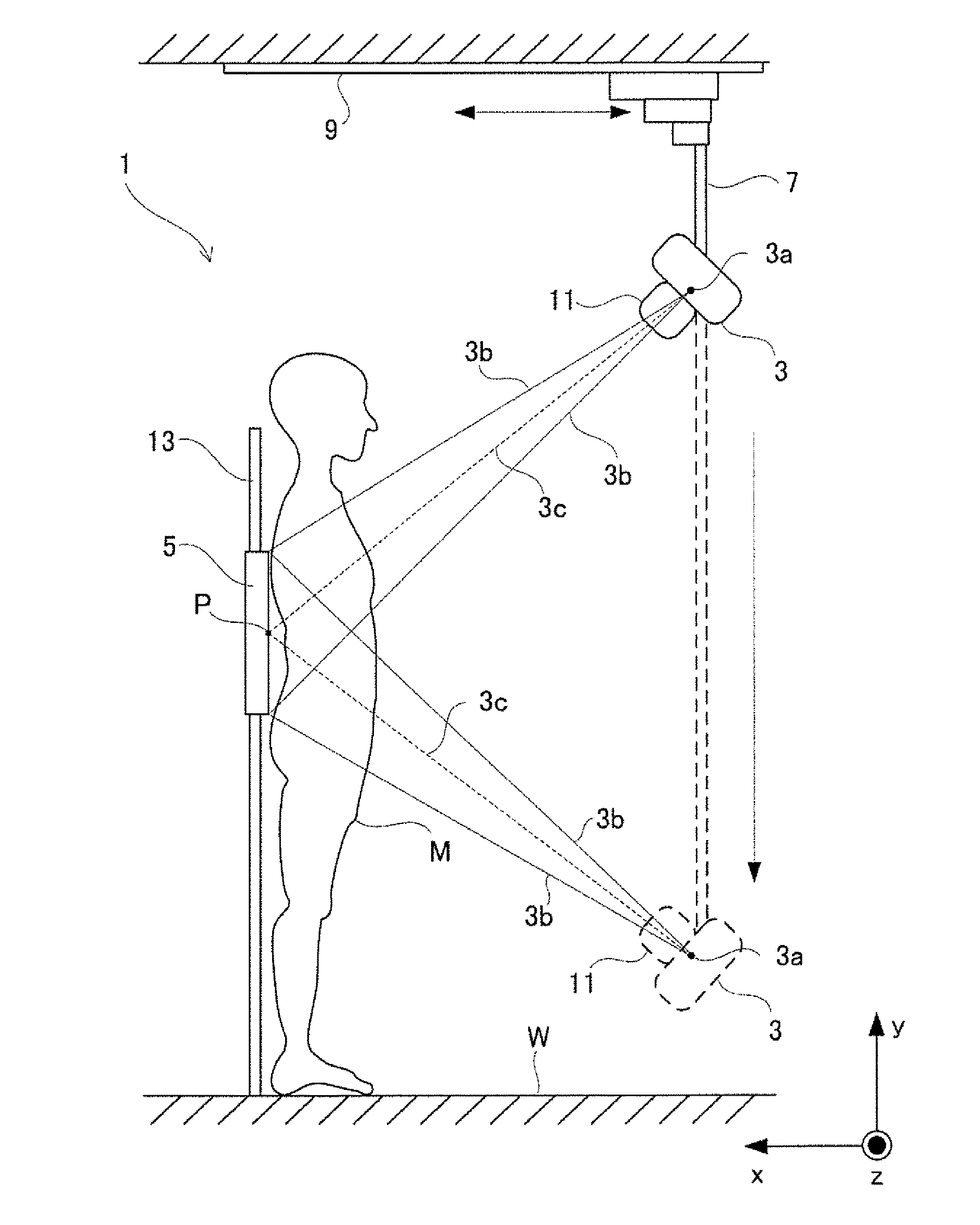
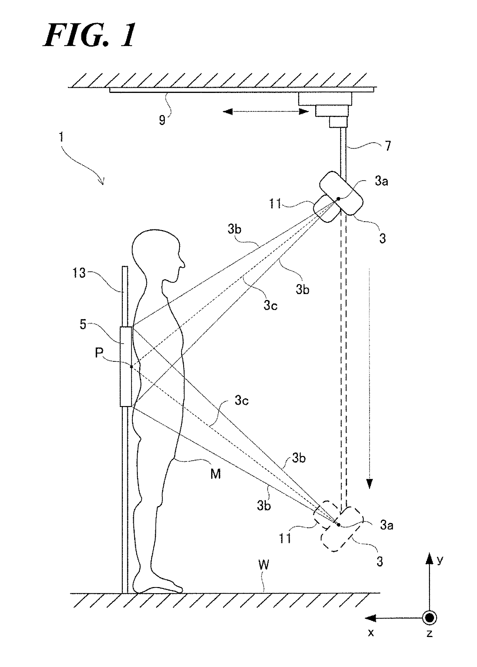
Specifically, it is likely problematic for the conventional radiation tomography imaging devices because the radiation tomography imaging may not be efficiently performed depending on parameters including the height F between the floor surface W and the center point P, the imaging distance, the irradiation swing angle θ and so forth.

Method used


Image

  • Radiation tomography device
  • Radiation tomography device
  • Radiation tomography device

Examples


embodiment 1

[0081]Referring to FIGs, the inventor sets forth the Embodiment 1 of the present invention. In addition, the inventor sets forth using X-ray as an example of radiations.

[0082](Illustration of the Entire Structure)

[0083]Referring to FIG. 1, the radiation tomography imaging device according to the aspect of the Embodiment 1 comprises an X-ray tube and an FPD 5 arranged facing each other as sandwiching the subject M. The X-ray tube 3 is supported by the X-ray tube supporting element 7 and irradiates the X-ray 3b from the X-ray focus 3a to the subject M. A base of the X-ray tube supporting element 7 is installed on the ceiling of the examination room and moves horizontally along with a rail 9 installed in the x-direction The collimator 11 installed to the X-ray tube 3 limits X-rays irradiated from the X-ray focus point 3a to a pyramid-like cone shape.

[0084]The FPD 5 is installed to the support post 13 vertically standing from the floor of the examination room so as to be movable freely ...

embodiment 2

[0146]Next, referring to FIGs, the inventors set forth the Embodiment 2 of the present invention. In addition, the inventor skips the detail description of the structure that is the same as the structure of a radiation tomography imaging device 1 according to the aspect of the Embodiment 1 but marking the same reference sign.

[0147](Characteristic Structure Relative to Embodiment 2)

[0148]The radiation tomography imaging device according to the aspect of the Embodiment 2, the main control element 31 comprehensively controls the X-ray tube moving mechanism 15 and the X-ray tube rotation mechanism 23 so that the X-ray tube 3 can move synchronously the FPD 5 during X-ray tomography imaging. Specifically, referring to FIG. 9, the X-ray tube moving mechanism 15 moves the X-ray tube 3 from the position indicated by the solid line to the position indicated by the broken line in the y-direction in the straight line and an FPD moving mechanism 23 moves the FPD 5 from the position indicated by ...

embodiment 3

[0195]Next, referring to FIGs, the inventors set forth the Embodiment 3 of the present invention. Further, the configuration and steps of an operation according to the aspect of the Embodiment 3 are the same as the radiation tomography imaging device 1 according to the aspect of the Embodiment 1 or the radiation tomography imaging device 1A according to the aspect of the Embodiment 2, so that the inventor skips the detail description.

[0196]However, according to the aspects of the Embodiment 1 and Embodiment 2, the imaging preparation position of the X-ray tube 3 coincides with the irradiation start position A of the X-ray tube 3. On the other hand, according to the aspect of the Embodiment 3 referring to FIG. 17A, the imaging preparation position of the X-ray tube 3 indicated by the sign Af is different from the position of the irradiation start position A of the X-ray tube 3. In such way, the Embodiment 3 is different from the Embodiment 1 and the Embodiment 2 with regard to the po...


PUM


Abstract

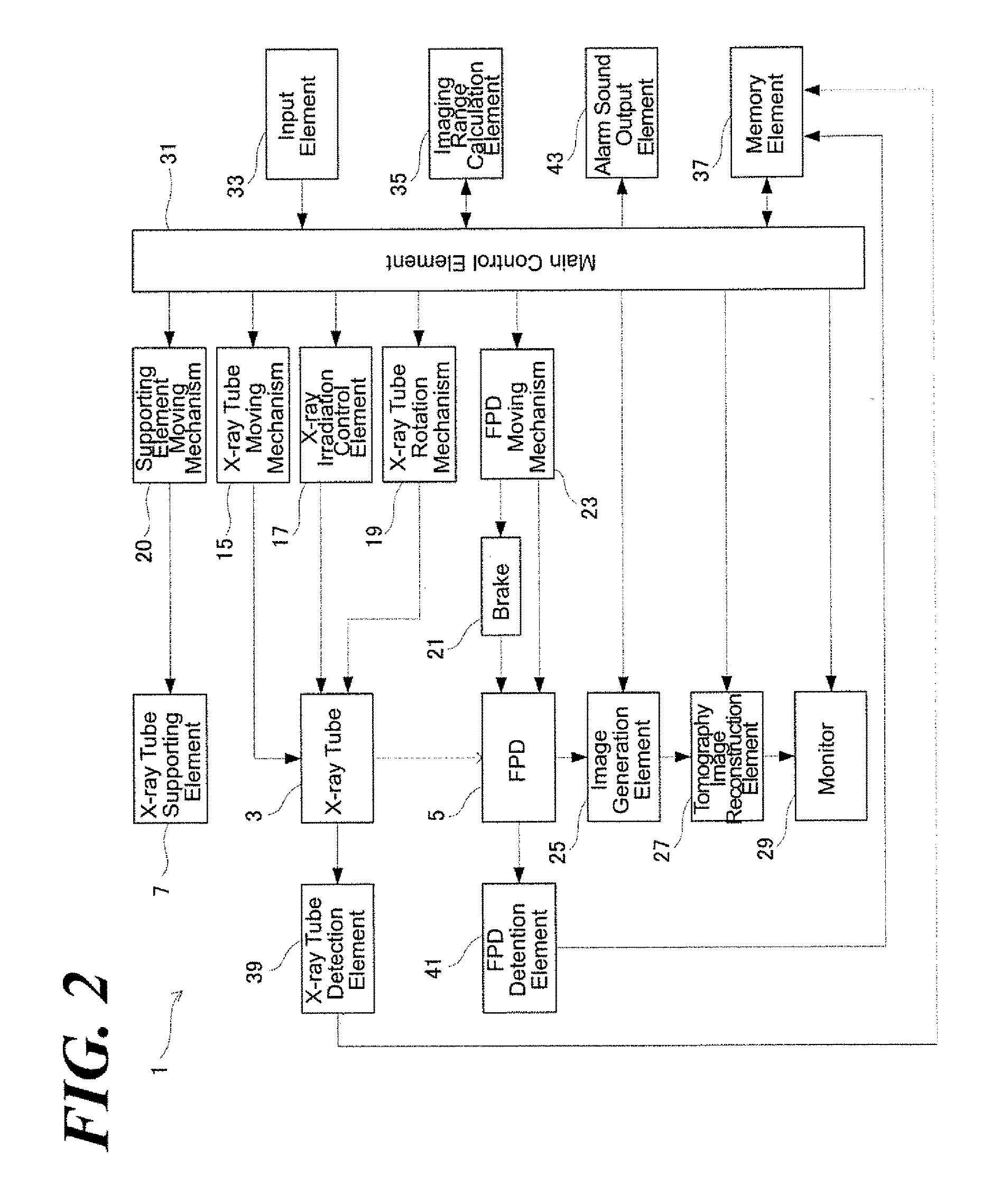
In a radiation tomography imaging device, the imaging range calculation element 35 calculates a possible imaging range of the FPD 5 based on the imaging distance G, the irradiation swing angle θ and the movable range SP of the X-ray tube 3. The operator can preliminarily calculate the possible imaging range of the radiation detection means prior to the X-ray tomography imaging because the imaging distance, the irradiation swing angle, and the movable range SP are all predetermined parameters. The possible imaging range FP of the FPD 5 is the positional range of the FPD 5 in which the X-ray tube 3 can acquire the X-ray tomography image without moving the X-ray tube 3 to the outside of movable range. Therefore, the radiation tomography imaging can start the X-ray tomography by assuredly moving the FPD 5 within the possible imaging range by referring to the preliminarily calculated possible imaging range of the FPD 5. As results, an incident in which the X-ray tube 3 moves out of the movable range SP and interferes the floor surface W and so forth can be avoided, so that the X-ray tomography imaging can be performed adequately.

Description

CROSS REFERENCE TO RELATED APPLICATIONS[0001]This application relates to and claims priority from PCT Ser. No.: PCT / JP2014 / 062108 filed May 1, 2014, the entire contents of which are incorporated herein by reference.FIGURE SELECTED FOR PUBLICATION[0002]FIG. 5BACKGROUND OF THE INVENTION[0003]Field of the Invention[0004]The present invention relates to a radiation tomography device having a radiation source and a radiation detector, and particularly relates to a technology by which a positional range of the radiation detector, which enables imaging of the radiation tomography image, is automatically calculated.[0005]Description of the Related Art[0006]In medical fields, a radiation imaging device based on an imaging technology so-called tomosynthesis, which is a device to obtain a tomographic image of a cross section of a subject by utilizing a radiation, has been used (Patent Document 1, 2.) As for such radiation tomographic device, a radiation source and a radiation detector are in p...

Claims


Application Information

Patent Timeline
Patent Type & Authority Applications(United States)
IPC IPC(8): A61B6/00
CPCA61B6/547A61B6/40A61B6/4464A61B6/4452A61B6/46A61B6/5205A61B6/025
Inventor OKUNO, TOMOHARUSHIROTA, KEN
Owner SHIMADZU CORP
Learn More