
Exhaust device for engine

an exhaust valve and engine technology, applied in the direction of exhaust treatment, electric control, combustion engines, etc., can solve the problems of large distortion between the partition wall and the peripheral portion, cracks may occur in the partition wall, and the plate-shaped partition wall located between the low-speed exhaust passage and the high-speed exhaust passage may be distorted, so as to prevent breakage or damage of the exhaust valve device and suppress the effect of deterioration of the traveling performan

Active Publication Date: 2017-03-02
MAZDA MOTOR CORP
View PDF5 Cites 2 Cited by
  • Summary
  • Abstract
  • Description
  • Claims
  • Application Information

AI Technical Summary

Benefits of technology

The present invention provides an exhaust device for a vehicle mounted with a supercharger engine. The device prevents damage to the exhaust valve that adjusts the flow of exhaust gas to the supercharger due to thermal stress and prevents deterioration of the vehicle's performance in high-speed operating ranges.

Problems solved by technology

In the turbocharger engine described in the Publication, however, a plate-shaped partition wall located between the low-speed exhaust passages and the high-speed exhaust passages may be distorted due to thermal stress.
If the distortion is large, cracks may occur in the partition wall.
As a result, large distortion may occur between the partition wall and the peripheral portion due to a difference in the amount of thermal expansion, and cracks may occur in the vicinity of a boundary between the partition wall and the peripheral portion.
Further, when the exhaust variable valve is rendered unmovable in a closed state due to thermal distortion of the partition wall and the peripheral portion, or the like, the following drawback may occur.
Specifically, when the vehicle is in a high speed operating range, exhaust gas, which should flow through the high-speed exhaust passages, may collide against the exhaust variable valve, and the flow of exhaust gas may stagnate.
As a result, exhaust gas may not be smoothly discharged from the exhaust port of the engine body, and a combustion chamber of the engine may cause combustion failure.
This may deteriorate the traveling performance in the high speed operating range.

Method used


Image

  • Exhaust device for engine
  • Exhaust device for engine
  • Exhaust device for engine

Examples


Embodiment Construction

[0017]In the following, an embodiment of the present invention is described referring to the drawings.

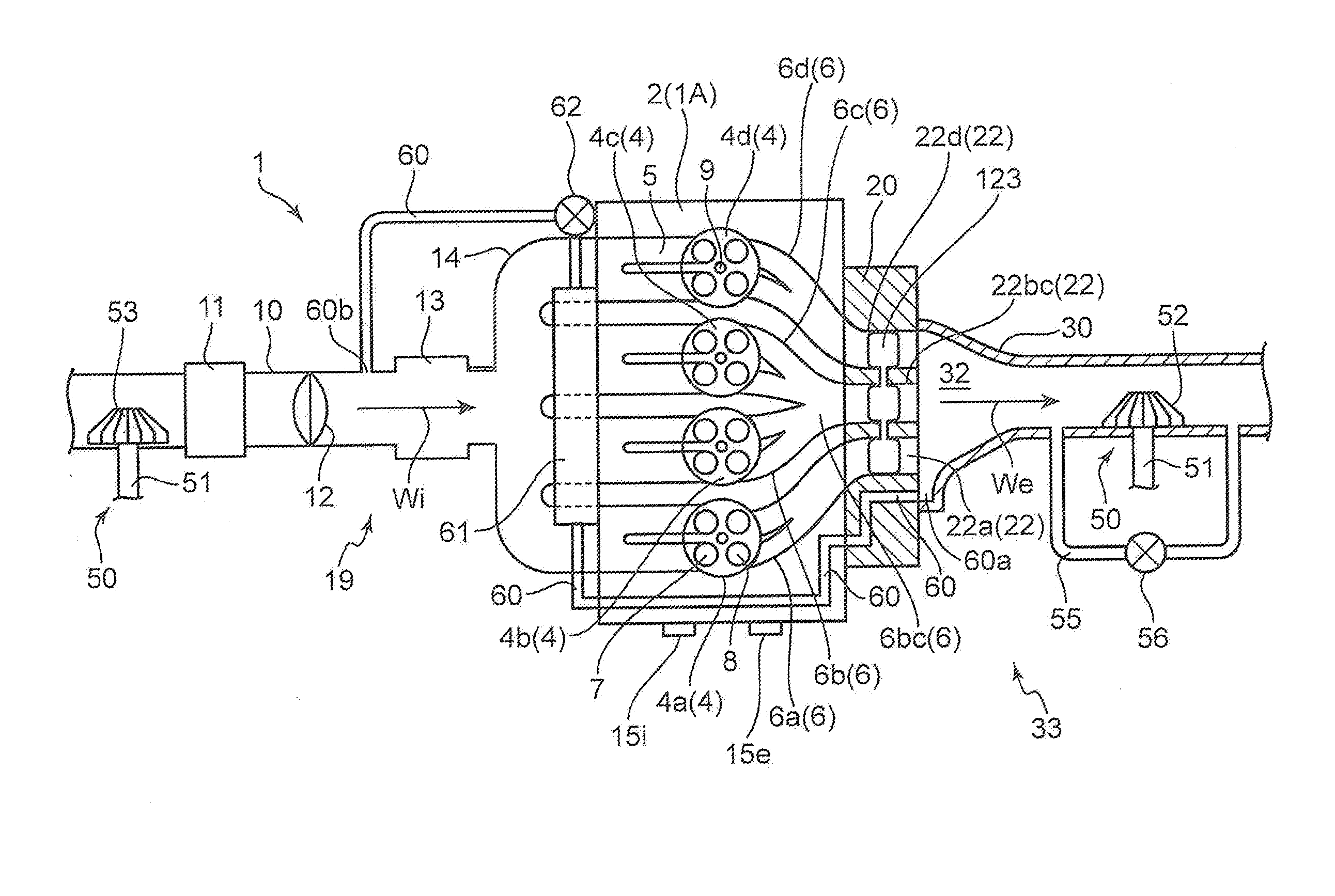
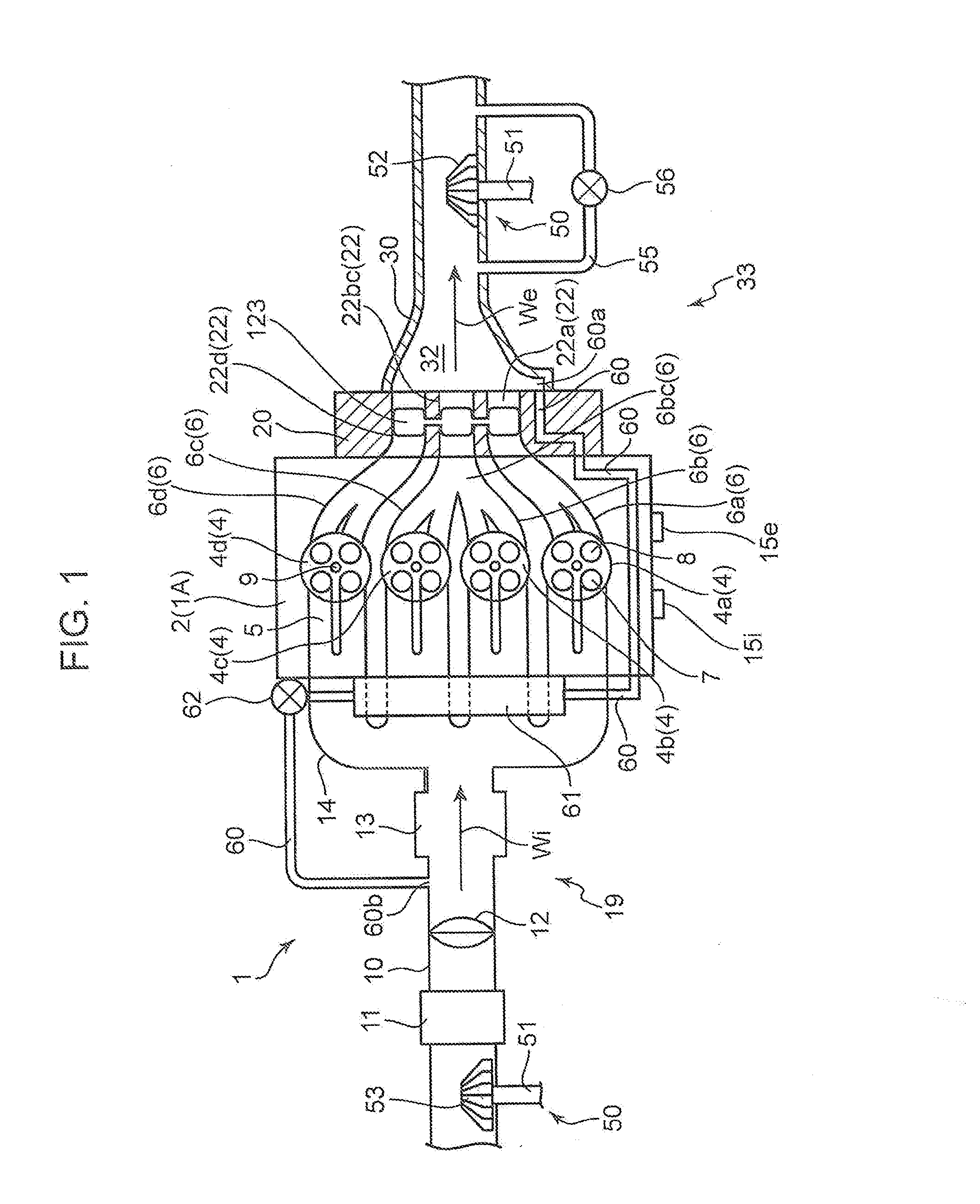
[0018]FIG. 1 illustrates an overall configuration of an engine 1 according to the embodiment. In the embodiment, the terms “upstream” and “downstream” are expressed in terms of a flow of gas flowing through a relevant portion.

[0019]The engine 1 is an in-line 4-cylinder 4-cycle spark-ignition engine to be mounted in a vehicle, as a power source for traveling. The engine 1 is provided with an engine body 1A including a cylinder block (not illustrated) and a cylinder head 2 disposed on an upper surface of the cylinder block as main members, an intake passage 19 for guiding intake air Wi to the engine body 1A, an exhaust passage 33 for discharging exhaust gas We from the engine body 1A, and a turbocharger 50 for supplying intake air Wi to the engine body 1A.

[0020]The turbocharger 50 has a well-known structure. Specifically, the turbocharger 50 is configured such that a turbine 52 provid...


PUM


Abstract

An exhaust device for an engine, interposed between an engine body, and a supercharger to be driven by a pressure of exhaust gas to be discharged from the engine body, includes a first exhaust passage and a second exhaust passage which introduce exhaust gas to the supercharger; a partition wall disposed between the first exhaust passage and the second exhaust passage, and configured to partition the first exhaust passage and the second exhaust passage from each other; and a valve disposed within the second exhaust passage, and configured to adjust the flow rate of exhaust gas flowing through the second exhaust passage. The partition wall includes a communication portion for communicating between the first exhaust passage and the second exhaust passage.

Description

FIELD OF THE INVENTION[0001]The present invention relates to an exhaust device for an engine.BACKGROUND ART[0002]Conventionally, in a vehicle mounted with a turbocharger engine, a study about enhancing the supercharging performance of a turbocharger is carried out. For instance, Japanese Unexamined Patent Publication No. 2014-84757 discloses an engine, in which the flow rate of exhaust gas to be introduced to a turbocharger is controlled by changing the flow area of exhaust gas within an exhaust passage according to a traveling condition of a vehicle to enhance the supercharging performance of a turbocharger.[0003]Specifically, the turbocharger engine described in the Publication is provided with an engine body, an exhaust valve device connected to an exhaust port of the engine body, and a turbocharger connected to the downstream end of the exhaust valve device. The exhaust valve device is provided with a device body including three low-speed exhaust passages arranged in the cylinde...

Claims


Application Information

Patent Timeline
Patent Type & Authority Applications(United States)
IPC IPC(8): F02B37/18F01N13/10F02D9/04
CPCF02B37/186F01N13/107F02D9/04F02D9/10F01N13/10F02D41/0007F01N2240/36F01N2260/10F01N2340/06F01N2390/02F02B37/02F02B37/22Y02T10/12
Inventor SUEKUNI, EINOSUKEUMEMURA, JUNJITSUJITA, SHUHEIMIHARA, MAKOTOFUJIYAMA, TOMOAKIHAMADA, HIROYUKIHADAMA, KOUJIIKEDA, MASAHIRO
Owner MAZDA MOTOR CORP
Learn More