System for suppressing acoustic noise within a gas turbine combustor

a technology of combustor and gas turbine engine, which is applied in the field of gas turbine engines, can solve the problems of reducing the operability margin of the turbofan engine, negatively affecting the compressor stall margin, and increasing the external combustion noise or growl. , to achieve the effect of suppressing acoustic nois

Active Publication Date: 2017-03-02
GENERAL ELECTRIC CO
View PDF2 Cites 16 Cited by
  • Summary
  • Abstract
  • Description
  • Claims
  • Application Information

AI Technical Summary

Benefits of technology

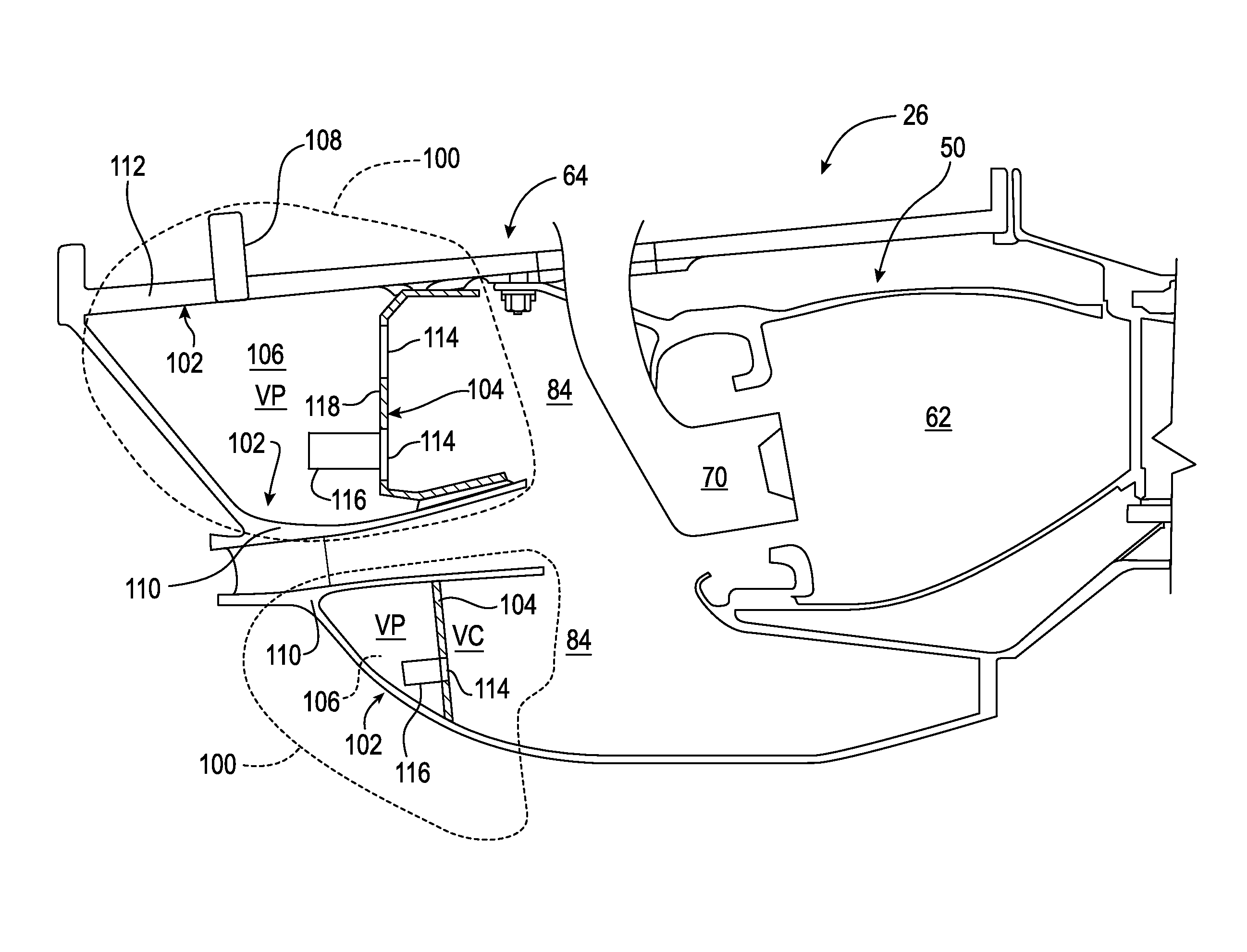
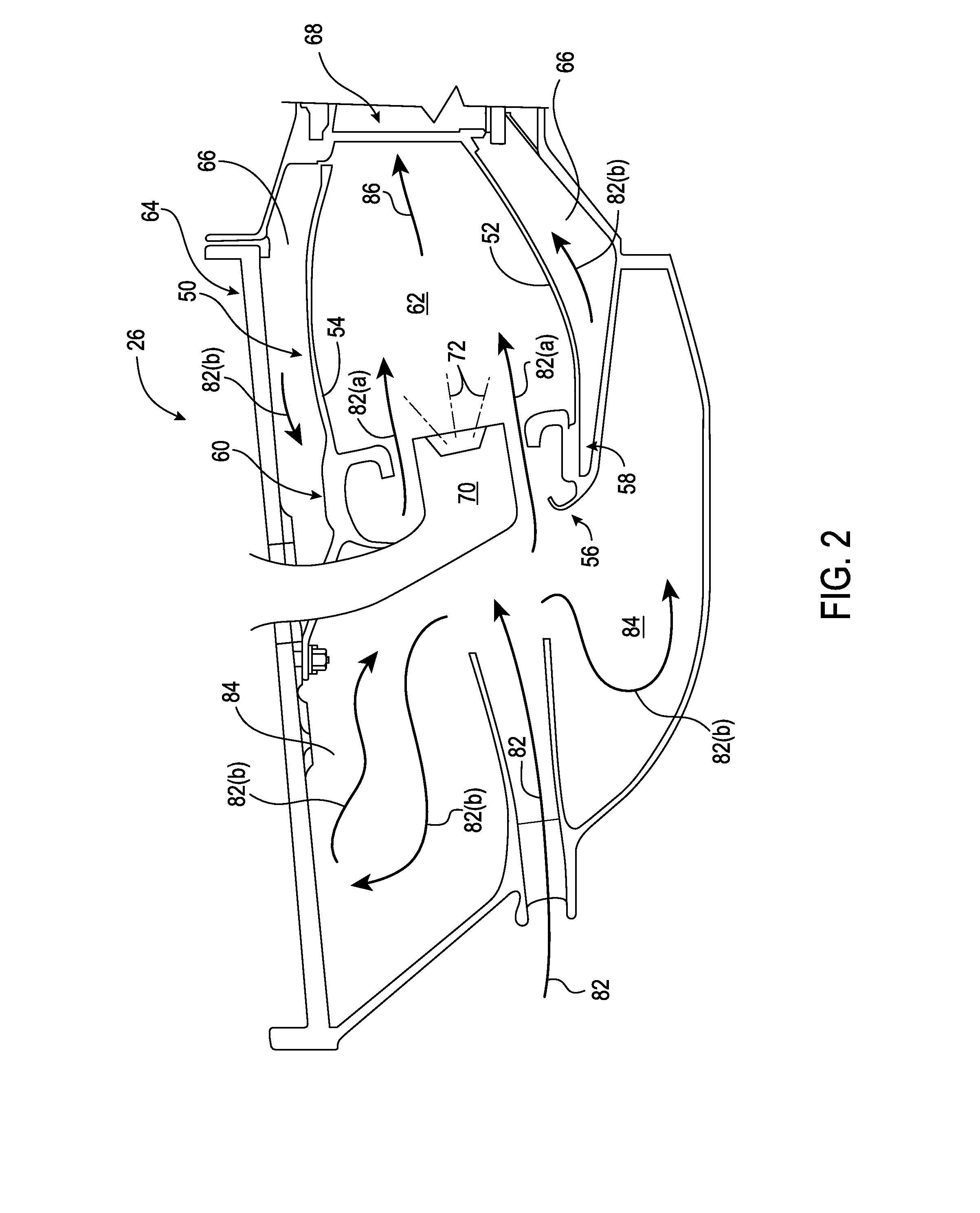
[0008]In one aspect the present subject matter is directed to a system for suppressing acoustic noise within a combustion section of a gas turbine. The system includes at least one static structure disposed forward of a combustion chamber defined within the combustion section. The static structure at least partially defines a diffuser cavity upstream of the combustion chamber. A baffle plate is coupled...

Problems solved by technology

Low frequency to intermediate frequency combustion dynamics (50-250 Hz) such as those that occur during engine startup and/or during a low power to idle operating condition may negatively impact compressor stall margin, reduce operability margin of the turbofan engine and/o...

Method used


Image

  • System for suppressing acoustic noise within a gas turbine combustor
  • System for suppressing acoustic noise within a gas turbine combustor
  • System for suppressing acoustic noise within a gas turbine combustor

Examples


Embodiment Construction

[0024]Reference will now be made in detail to present embodiments of the invention, one or more examples of which are illustrated in the accompanying drawings. The detailed description uses numerical and letter designations to refer to features in the drawings. Like or similar designations in the drawings and description have been used to refer to like or similar parts of the invention. As used herein, the terms “first”, “second”, and “third” may be used interchangeably to distinguish one component from another and are not intended to signify location or importance of the individual components. The terms “upstream” and “downstream” refer to the relative flow direction with respect to fluid flow in a fluid pathway. For example, “upstream” refers to the flow direction from which the fluid flows, and “downstream” refers to the flow direction to which the fluid flows.

[0025]Each example is provided by way of explanation of the invention, not limitation of the invention. In fact, it will ...


PUM


Abstract

In one aspect the present subject matter is directed to a system for suppressing acoustic noise within a combustion section of a gas turbine. The system includes at least one static structure disposed forward of a combustion chamber defined within the combustion section. The static structure at least partially defines a diffuser cavity upstream of the combustion chamber. A baffle plate is coupled to the static structure. The baffle plate and the static structure at least partially define an air plenum within the combustion section forward of the combustion chamber. The baffle plate includes an aperture that provides for fluid communication between the diffuser cavity and the air plenum. The at least one static structure and the baffle plate define a Helmholtz resonator within the combustion section.

Description

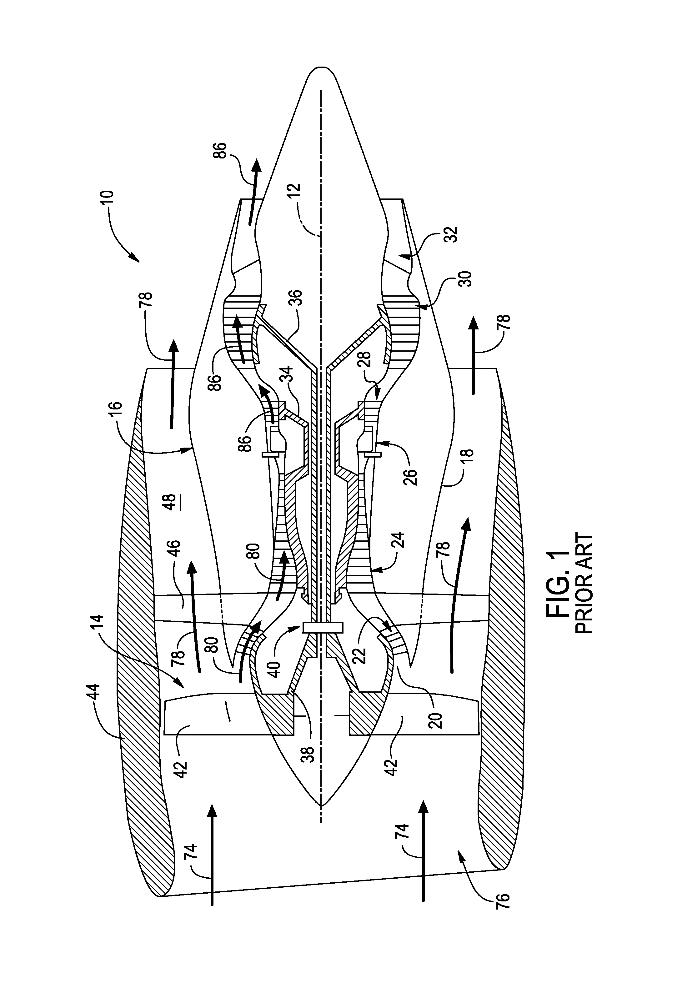
FIELD OF THE INVENTION[0001]The present subject matter relates generally to a gas turbine engine. More particularly, the present subject matter relates to a system for suppressing acoustic noise within a combustor of the gas turbine engine.BACKGROUND OF THE INVENTION[0002]A high-bypass type turbofan engine generally includes a fan section and a core gas turbine engine. The gas turbine engine includes, in serial flow order, a low pressure compressor, a high pressure compressor, a combustion section, a high pressure turbine and a low pressure turbine. A high pressure shaft couples the high pressure compressor to the high pressure turbine. A low pressure shaft extends coaxially within the high pressure shaft and couples the low pressure compressor to the low pressure turbine.[0003]The fan section includes a plurality of fan blades coupled to a fan shaft and disposed upstream from an inlet of the low pressure compressor. The fan shaft may be coupled to the low pressure shaft either dire...

Claims


Application Information

Patent Timeline
IPC IPC(8): F02C7/24F01D9/02F02C3/04F23R3/42F02C7/04F02C9/18
CPCF05D2240/24F02C7/24F02C7/04F02C9/18F02C3/04F05D2240/35F01D9/02F05D2220/36F05D2260/963F05D2220/32F23R3/42F02C7/045F01D25/04F02C3/14F05D2260/964F23R3/04F23R2900/00014Y02T50/60
Inventor KIM, KWANKOOHAN, FEIGRAHAM, OWEN
Owner GENERAL ELECTRIC CO
Why Eureka
Try Eureka