Radial position sensor

a position sensor and radial technology, applied in the direction of converting sensor output, mechanical energy handling, instruments, etc., can solve the problem that the rotor is never perfectly cylindrical, and achieve the effect of less copper and less sensitive to rotor surface defects

Active Publication Date: 2017-03-09
SKF MAGNETIC MECHATRONICS
View PDF3 Cites 6 Cited by
  • Summary
  • Abstract
  • Description
  • Claims
  • Application Information

AI Technical Summary

Benefits of technology

[0010]The invention intends to solve these drawbacks by proposing a radial position sensor that is easier to manufacture, while offering the same measuring accuracy.
[0012]Thanks to the invention, the sensor includes two times less electromagnets than prior art radial position sensors, for a similar measuring accuracy. There is then two times less coils to wind and less copper is used. Further, coils are more spaced from each other so that winding can be performed automatically. Besides, the sensor is less sensitive to rotor surface defects. This sensor provides the same performances in terms of linearity, sensitivity and power consumption than a corresponding sensor from prior art. In other words, an 8 poles radial position sensor according to the invention can replace a 16 poles radial position sensor from prior art and a 4 poles radial position sensor according to the invention can replace an 8 poles radial position sensor from prior art.

Problems solved by technology

Indeed, the rotor is never perfectly cylindrical.

Method used


Image

  • Radial position sensor
  • Radial position sensor
  • Radial position sensor

Examples


Embodiment Construction

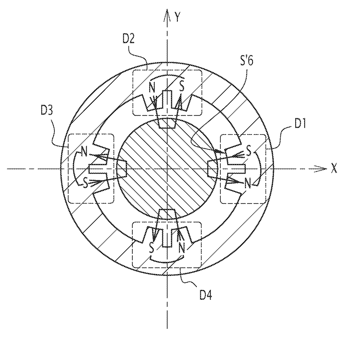
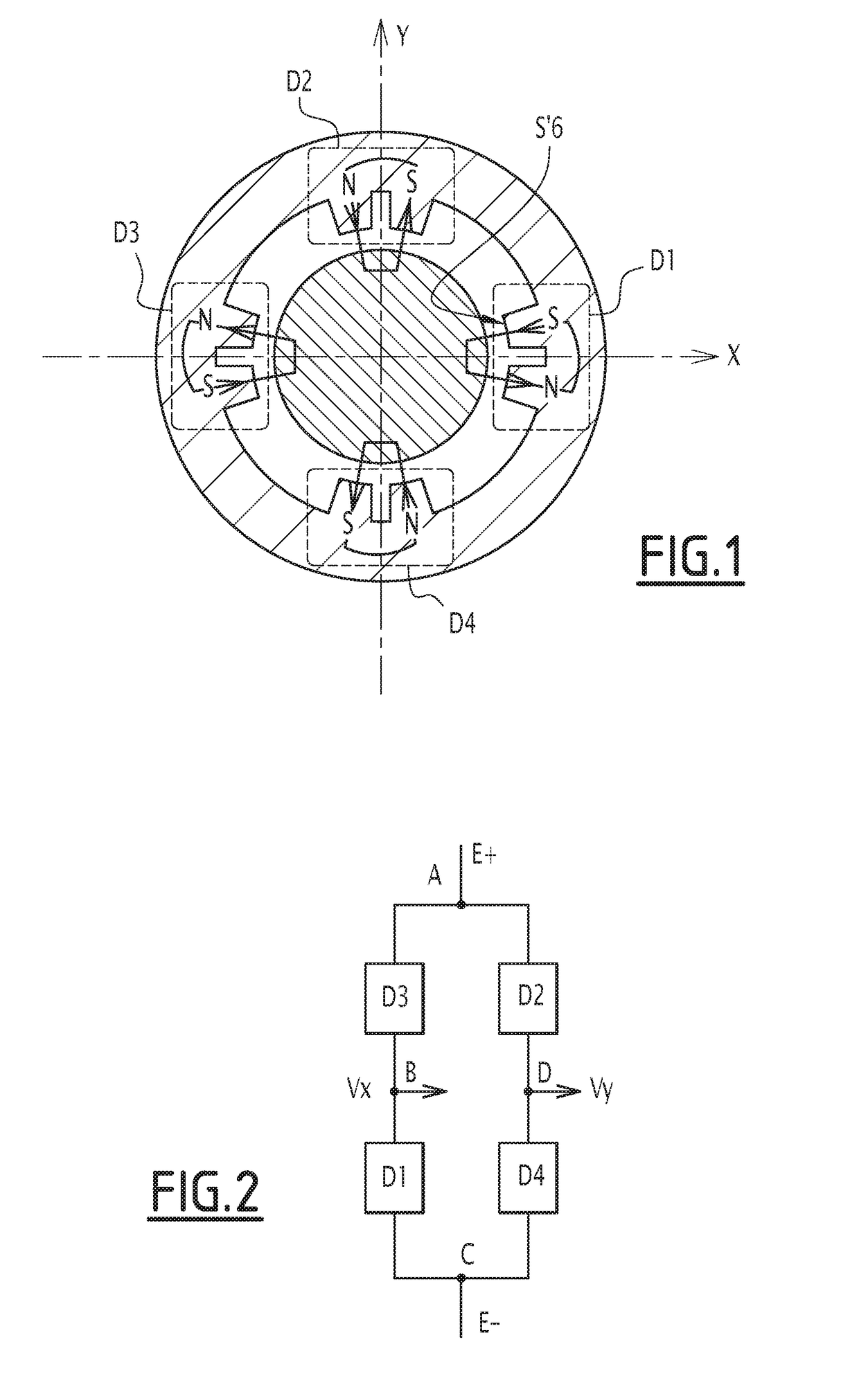
[0025]FIG. 5 represents a radial position sensor for measuring the radial position of a rotor 4 within a stator 2. The rotor 4 is made of ferromagnetic material. The sensor includes four poles. Each pole is formed by an electromagnet Z1, Z2, Z3 or Z4. The electromagnets Z1, Z2, Z3 and Z4 are arranged on the inner surface of stator 2. The sensor is then a 4 poles radial position sensor. As the sensor of FIG. 1, this sensor is capable of rejecting even harmonics representative of rotor defects. Indeed, the rotor is never perfectly cylindrical.

[0026]The electromagnets Z1, Z2, Z3 and Z4 include each a non-represented coil that is wound around a core 6 protruding internally with respect to the inner surface of the stator 2. Each coil has the same number of turns. This number of turns is the same than that of coils belonging to prior art sensors. The electromagnets Z1 to Z4 are distributed with alternating magnetic polarities N, S around the entire circumference of the stator 2 and with a...


PUM


Abstract

This radial position sensor measures the radial position of a rotor within a stator. The sensor provides measuring means for measuring the position of the rotor along a first axis radial to a rotation axis of the rotor and along a second axis perpendicular to the first axis. The measuring means includes four magnetic poles, among which two poles are diametrically opposed along the first axis and two other poles are diametrically opposed along the second axis, the magnetic poles distributed, on the inner surface of the stator, with alternating magnetic polarities around the circumference of the stator. Alternatively, the measuring means includes eight magnetic poles distributed, on the inner surface of the stator, with alternating magnetic polarities around the circumference of the stator and are arranged so that each pole deviates by an angle of approximately 30° from the nearest axis among the first axis and the second axis.

Description

CROSS REFERENCE TO RELATED APPLICATIONS[0001]This application claims priority to European patent application no. 15306373.0 filed on Sep. 9, 15, the contents of which are fully incorporated herein by reference.FIELD OF THE INVENTION[0002]The invention concerns a radial position sensor for measuring the radial position of a rotor within a stator. In particular, this sensor may be integrated to an electrical rotary machine or to a magnetic bearing, both comprising a fixed part, i.e. a stator, and a rotating part, i.e. a rotor.BACKGROUND OF THE INVENTION[0003]FIG. 1 represents an 8 poles radial position sensor from prior art. This sensor is capable of rejecting even harmonics representative of rotor defects. Indeed, the rotor is never perfectly cylindrical. The sensor includes eight magnetic poles arranged on the inner surface of the stator. Each pole is formed by an electromagnet. The electromagnets are divided into four pairs. The electromagnets of each pair have opposed magnetic pol...

Claims


Application Information

Patent Timeline
Patent Type & Authority Applications(United States)
IPC IPC(8): G01D5/20H02K7/09H02K11/215
CPCG01D5/2046H02K7/09H02K11/215G01D5/2013
Inventor DUPUIS, YVESDA SILVA, JOAQUIM
Owner SKF MAGNETIC MECHATRONICS
Why Eureka
Try Eureka