Intelligent shading object movement based on sun sensor intensity

a technology of intelligent shading and sensor intensity, applied in the direction of computer control, optical radiation measurement, instruments, etc., can solve the problems of inability to open or deploy interconnected unitary frames, inability to adapt to changing environmental conditions or user's desires, and inflexible or modifiable current sun shading devices

Inactive Publication Date: 2017-03-16
SHADECRAFT INC
View PDF5 Cites 22 Cited by
  • Summary
  • Abstract
  • Description
  • Claims
  • Application Information

AI Technical Summary

Problems solved by technology

However, current sun shading devices do not appear to be flexible or modifiable or able to adapt to changing environmental conditions or user's desires.
An interconnected unitary frame may not be able to be opened or deployed in a situation where only a portion or several portions of the shading object are necessary to be deployed.

Method used


Image

  • Intelligent shading object movement based on sun sensor intensity
  • Intelligent shading object movement based on sun sensor intensity
  • Intelligent shading object movement based on sun sensor intensity

Examples


third embodiment

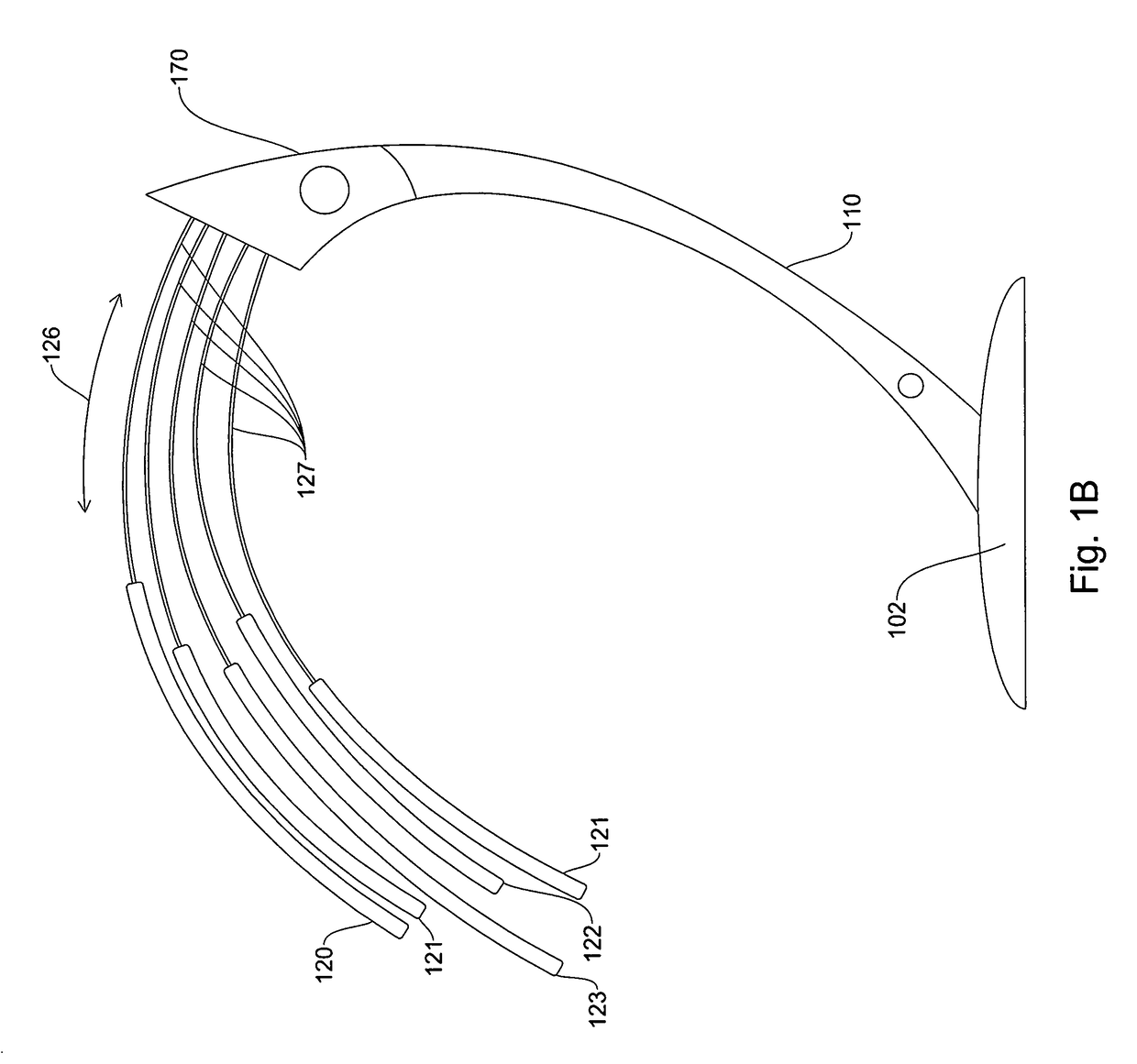
[0093]FIG. 9 discloses a method of operation for a shading object according to an embodiment. In step 905, a base unit is deployed. In step 910, in embodiments, a base unit may have weights added into compartments of a base unit. In step 915, in an embodiment, detachable support units are placed into holders in the base unit. In step 920, in an embodiment, a controller or processor may receive a command and one or more support units may move from a rest position to a shading or deployed position. In step 925, in embodiments, a controller or processor may receive a command and move support units from a shading position to a rest position.

[0094]In embodiments, in step 930, a sunlight sensor may detect an intensity and / or direction of sunlight. In step 935, a controller or processor may receive the signal from a sunlight sensor and may send a signal and / or commands directly, or indirectly, to rotate a base unit (and thus support units and shading elements) in a clockwise (or counterclo...

fourth embodiment

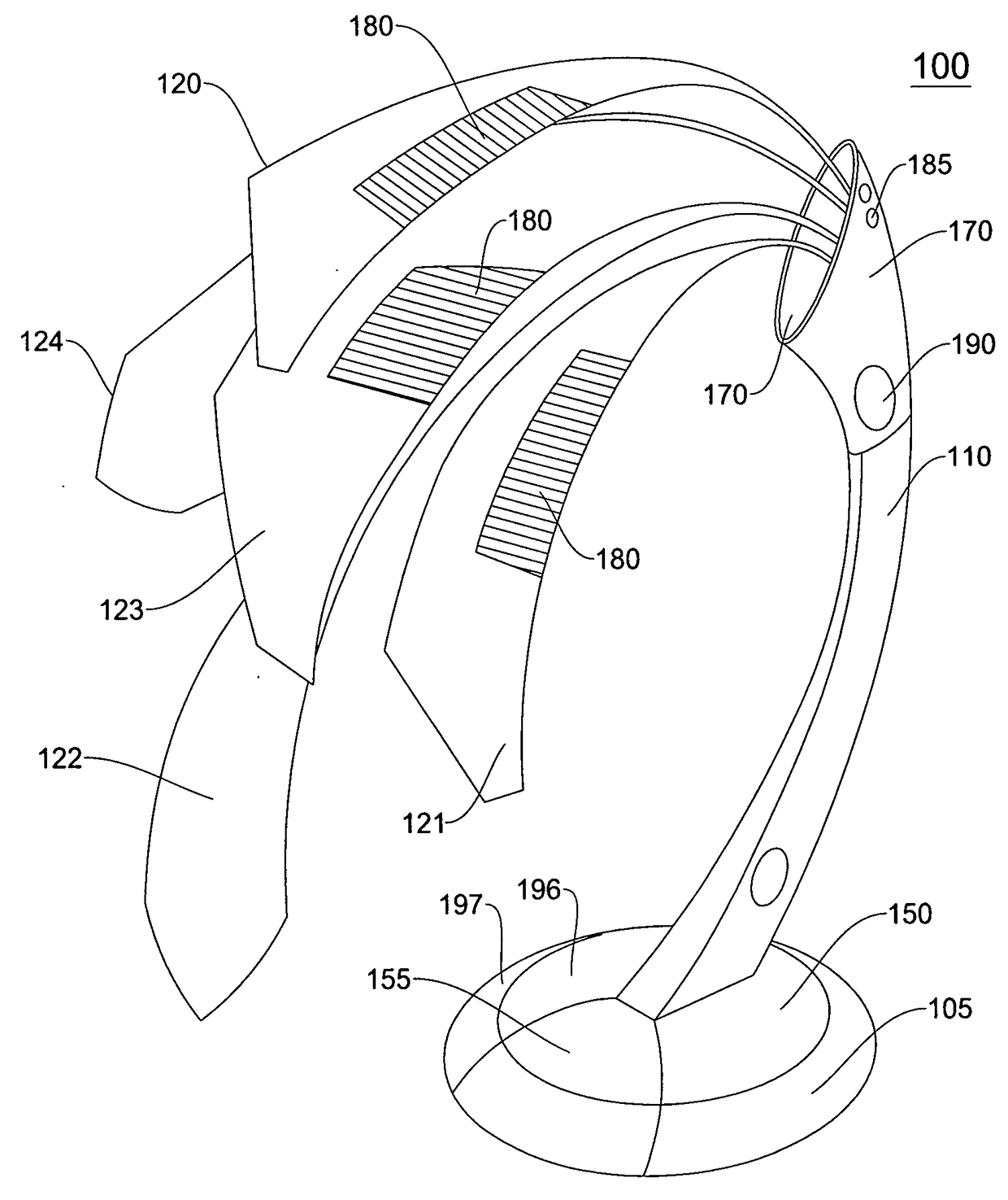
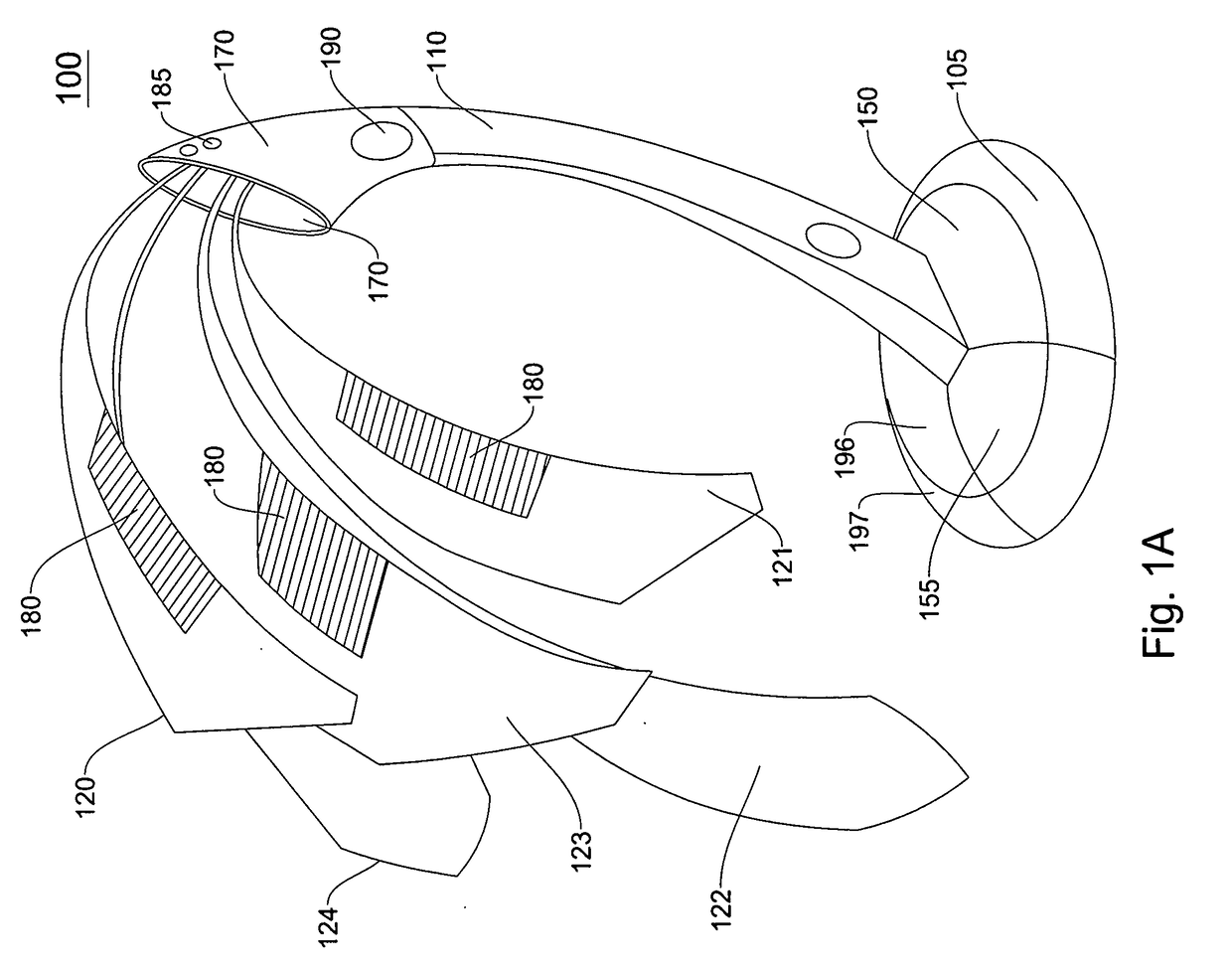
[0095]FIG. 10A illustrates an intelligent shading object. In an embodiment, shading object 1000 may comprise a base unit 1010, a support unit 1017, a telescope support housing 1025, a plurality of telescoping rods 103010311032, and / or a shading element 1040. In an embodiment, an intelligent shading object may also include at least one photo cell 1060 and / or a light sensor 1050.

[0096]In an embodiment, a base unit 1010 may include weight compartments 1011 for housing weights to provide additional support to a base unit 1010, when a shading element 1040 is deployed. In an embodiment, weights may be removable and may fit into weight compartments. In an embodiment, a base unit 1010 may also include a rotation unit 1015. In an embodiment, a rotation unit 1015 may be circular in shape and may be located in an interior surface of the base unit 1010, as illustrated in FIG. 10A.

[0097]In an embodiment, a support unit 1017 may be connected or coupled to a base unit 1010. In embodiments, a suppo...


PUM


Abstract

An intelligent umbrella includes a light sensor to generate a light intensity measurement, a motor to move the light sensor about an azimuth axis, the light sensor generating a plurality of light intensity measurements and associated locations. The intelligent umbrella also includes a controller to receive the plurality of light intensity measurements from the light sensor, and to identify a highest light sensor measurement of the plurality of light sensor measurements and an associated location. The controller generates and communicates a command including the associated location to a motor, which receives the command and moves the light sensor to the associated location. The controller moves a light sensor about an elevation axis, determines a peak intensity value and corresponding elevation location, and moves the light sensor to the corresponding elevation location.

Description

RELATED APPLICATIONS[0001]This is a divisional application of non-provisional application Ser. No. 14 / 810,380, filed Jul. 27, 2015 and entitled “Intelligent Shading Objects,” which claims priority to provisional application Ser. No. 62 / 165,869, filed May 22, 2015, entitled “Intelligent Shading Objects,” the disclosures of which both are hereby incorporated by reference.BACKGROUND[0002]1. Field[0003]The subject matter disclosed herein relates to a methods and systems for providing shade or protection from weather and more specifically to an intelligent sun shading object.[0004]2. Information / Background of the Invention[0005]Conventional sun shading devices usually are comprised of a supporting frame and an awning or fabric mounted on the supporting frame to cover a predefined area. For example, a conventional sun shading device may be an outdoor umbrella or an outdoor awning.[0006]However, current sun shading devices do not appear to be flexible or modifiable or able to adapt to chan...

Claims


Application Information

Patent Timeline
Patent Type & Authority Applications(United States)
IPC IPC(8): A45B25/16G01S3/786G05B15/02G01J1/42A45B23/00A45B17/00
CPCA45B25/165A45B23/00A45B17/00G05B15/02G01J1/4204G01J2001/4266A45B2025/003A45B2023/0093A45B2023/0012A45B2017/005G01S3/7861A45B25/143A45B2019/002A45B19/02A45B2023/0031A45B2019/026A45B19/08A45B25/16A45B2200/1018A45B2200/1027A45B25/18G01C17/00G01J1/42G01S19/14A45B19/04G01J1/44
Inventor GHARABEGIAN, ARMEN SEVADA
Owner SHADECRAFT INC
Why Eureka
Try Eureka